Introduction: Why EDM Dominates Mold Cavity Making
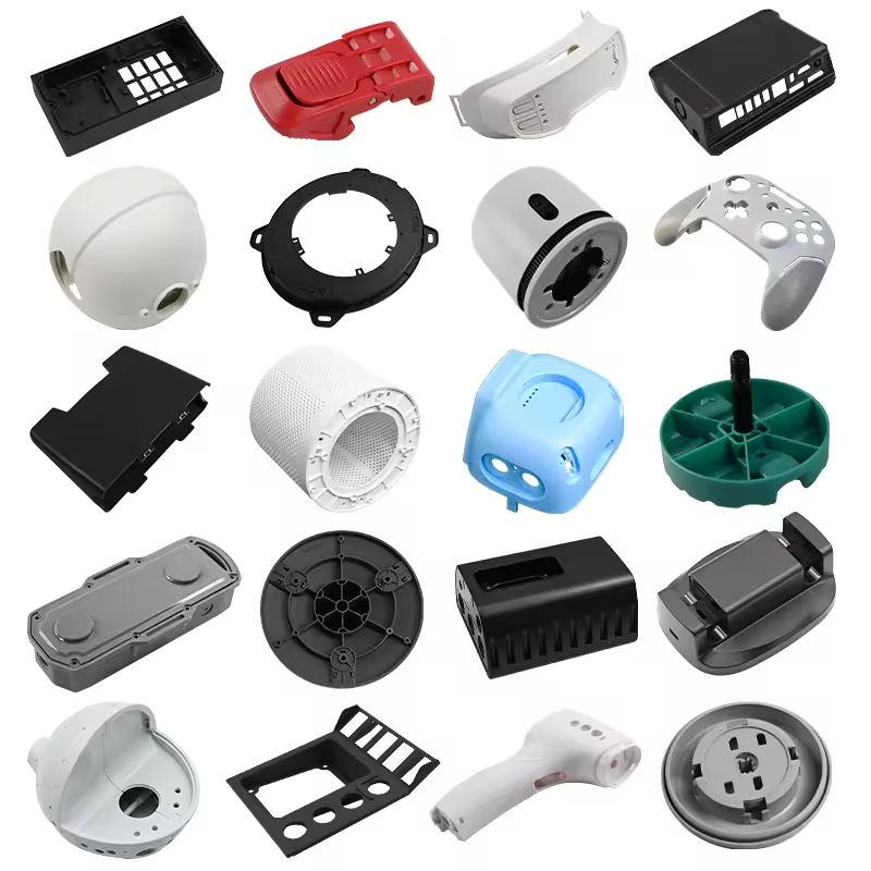
When it comes to creating complex mold cavities in hardened tool steel, Electrical Discharge Machining (EDM) remains unmatched. CNC milling struggles with sharp internal corners, deep narrow ribs, and materials hardened above 50 HRC. Sinker EDM??lso known as ram EDM or die-sinking EDM??olves all of these challenges by using spark erosion to remove material without mechanical cutting forces. This makes it the go-to process for injection mold cores, cavities, ribs, bosses, and intricate details that would be impossible or prohibitively expensive to mill.
How Sinker EDM Works: Spark Erosion Fundamentals
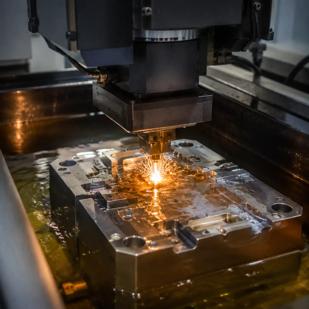
Sinker EDM operates on a simple but powerful principle: controlled spark erosion. The process uses a shaped electrode (typically graphite or copper) as a “reverse mold” that descends into the workpiece. Both electrode and workpiece are submerged in dielectric fluid (typically hydrocarbon oil), and a precisely controlled electrical potential is applied between them.
When the gap narrows to just a few microns, the dielectric fluid ionizes and a spark discharge occurs at temperatures reaching 8,000-12,000 degrees Celsius. This instantly vaporizes a microscopic particle of the workpiece material. The dielectric fluid then flushes away the debris and cools the gap before the next pulse. A servo-controlled Z-axis maintains the optimal spark gap??ypically 0.01 to 0.10 mm depending on the roughing or finishing settings.
Key parameters that define EDM performance:
- Overcut (spark gap): The space between electrode and workpiece where sparks occur??etermines dimensional offset between electrode and finished cavity.
- Pulse on-time: Duration of each spark??onger pulses remove more material but produce rougher surfaces.
- Pulse off-time: Cooling interval between sparks??oo short causes arcing and surface damage.
- Peak current: Amperage per pulse??igher current equals faster material removal but increased electrode wear.
- Duty cycle: Ratio of on-time to total cycle time??alanced for efficient material removal without unstable arcing.

Electrode Materials: Choosing the Right One for Your Mold
Electrode material selection directly impacts machining speed, surface finish, electrode wear, and overall mold accuracy. Each material has distinct tradeoffs that mold makers must weigh against part requirements and production volume. If the cavity finish target is still being debated, our surface finishing guide helps connect EDM outcome to final SPI and VDI requirements.
Graphite (Most Common for Mold Making)
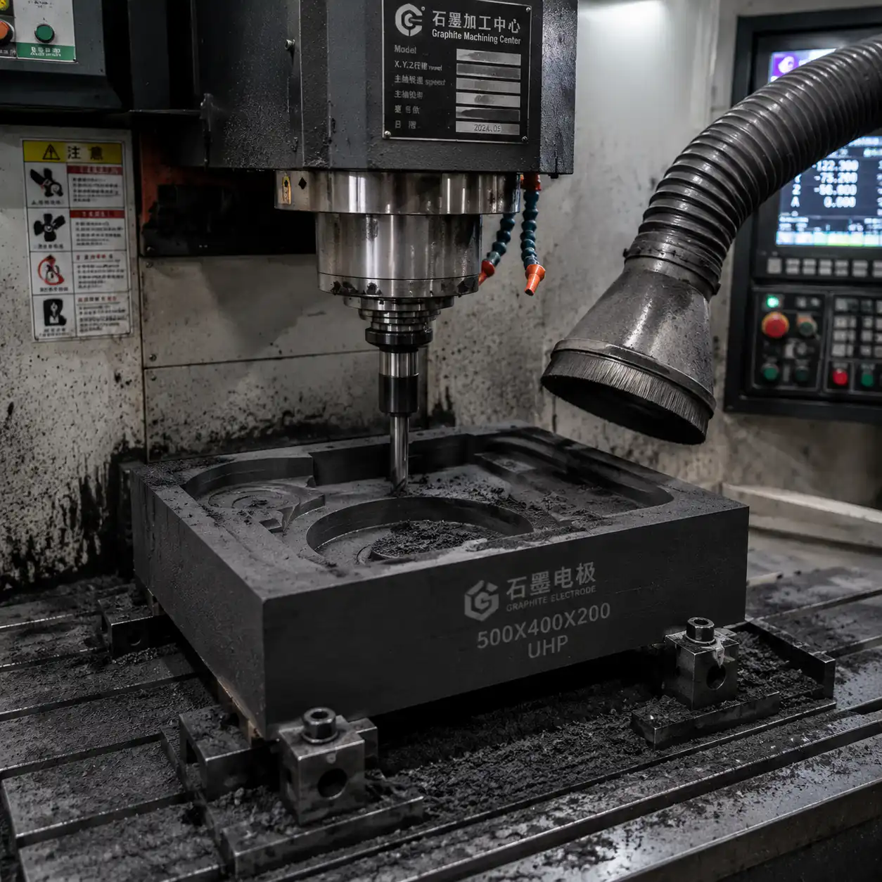
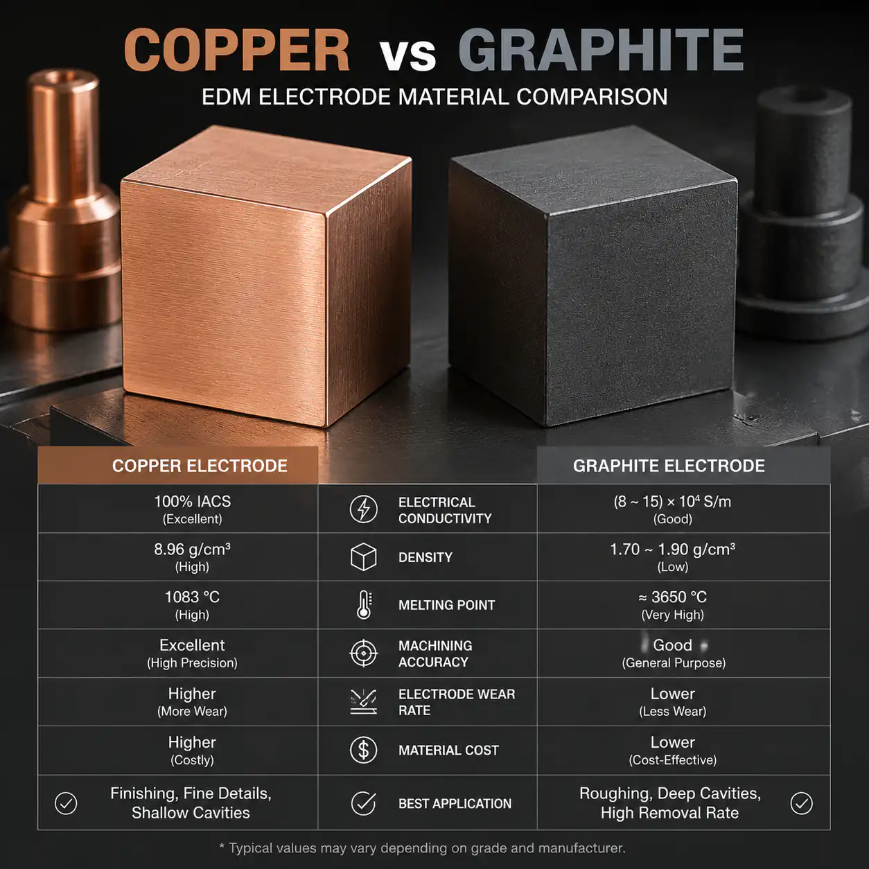
Graphite is the workhorse of mold cavity EDM for several compelling reasons. It offers the best combination of machinability, wear resistance, and thermal stability. Modern high-density graphites like Poco EDM-3 and ultrafine grades can hold detail down to 0.1 mm and achieve surface finishes below VDI 18 without secondary polishing.
- Common grades: EDM-1 (general roughing), EDM-3 (medium-fine detail), Poco series (ultra-fine finishing)
- Wear ratio: Less than 0.1% with proper flushing and polarity settings (positive electrode)
- Machinability: Excellent??raphite can be milled at high speeds with standard carbide tooling, enabling complex electrode geometries in a single setup.
- Limitations: Dust is abrasive and conductive??equires dedicated dust extraction on CNC mills. Not suitable for very small, fragile details (<0.05 mm) due to granular structure.
Copper
Copper electrodes deliver the best surface finish among common EDM electrode materials. They produce a mirror-like finish (VDI 6-8 equivalent) on steel and are favored for fine-detail medical and optical mold components. However, copper is significantly more difficult to machine than graphite??t is gummy, tends to gall on cutters, and requires slower machining speeds.
- Wear ratio: 0.5-2% depending on settings, higher than graphite.
- Best applications: High-gloss cosmetic surfaces, optical-grade cavities, small-detail inserts under 10 mm.
- Limitations: Higher thermal expansion can cause dimensional drift during long burn cycles. More expensive than standard graphite grades.
Copper-Tungsten (CuW)
Copper-tungsten combines the thermal conductivity of copper with the wear resistance of tungsten. It is the premium choice for micro-EDM and sharp-corner details where electrode integrity is critical. The high density means minimal wear even under aggressive roughing parameters.
- Wear ratio: Typically less than 0.1%, often under 0.05% for finishing operations.
- Best applications: Sharp corners, micro-ribs under 0.5 mm width, high-volume production electrodes that must maintain geometry across hundreds of burns.
- Limitations: Expensive (5-10x graphite), difficult to machine, and heavy.
Brass
Brass is rarely used for precision mold cavities due to rapid electrode wear. It finds niche use in wire EDM (brass wire is the standard consumable) and low-cost, low-volume roughing operations where electrode cost is the primary concern and dimensional accuracy can be compromised.
- Wear ratio: 10-30%??he highest of all electrode materials.
- Best applications: One-off prototypes, large roughing cavities where multiple electrodes are economically viable, educational/training environments.
Electrode Design Rules for Mold Making
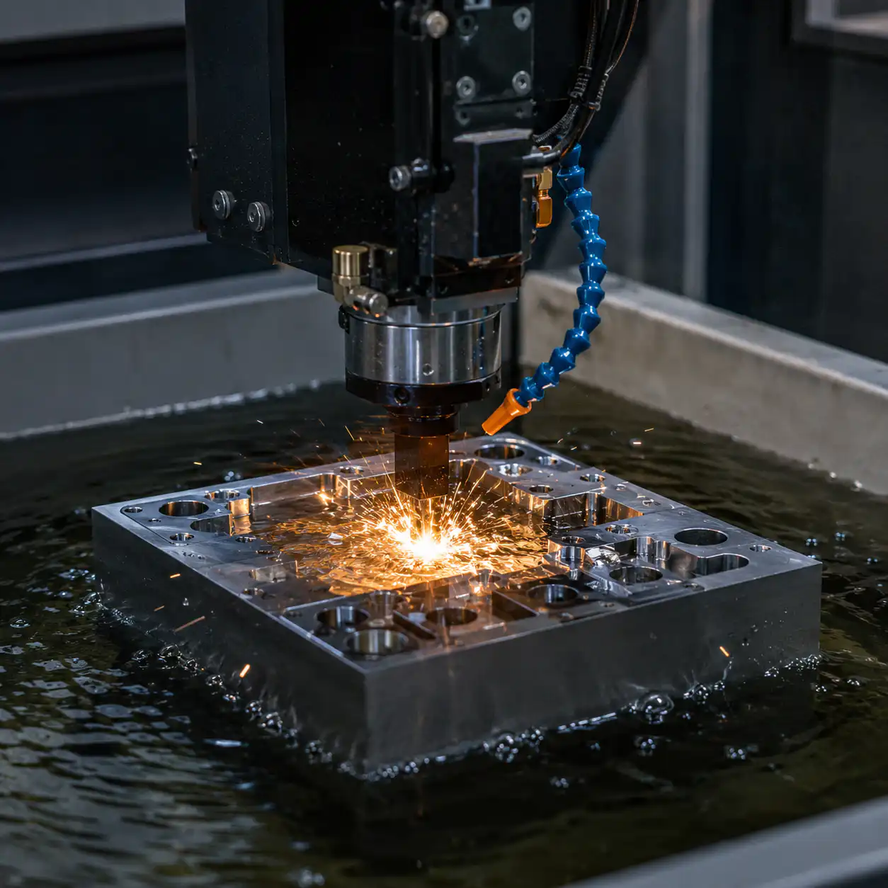
Electrode design is where EDM expertise separates average molds from exceptional ones. The electrode must be an exact negative of the cavity geometry??ut with critical dimensional offsets and strategic modifications that account for the physics of spark erosion.
Rule 1: Undersize by the Spark Gap
Every electrode must be undersized relative to the final cavity by the spark gap value. For roughing electrodes this might be 0.2-0.3 mm per side. For finishing electrodes it can be as small as 0.01-0.03 mm per side. Getting this undersize wrong by even 0.02 mm can scrap a mold insert worth thousands of dollars. Modern CNC EDM machines can compensate for this electronically (orbital motion), but mechanical undersize is still the standard for precision single-direction burns.
Rule 2: Orbital Motion Patterns
Orbital motion??here the electrode moves in a predetermined pattern during the burn??s essential for flushing, surface finish, and size control. Three main patterns are used:
- Spherical (3D orbital): The electrode traces a spherical path, ideal for complex 3D cavities where flushing is challenging from all directions. Produces isotropic surface finish.
- Cylindrical (2D circular): The electrode orbits in a circle in the XY plane. Best for pockets, ribs, and features where the primary spark gap is in the radial direction.
- Vector (linear): The electrode translates along a straight vector. Used for slot features, narrow ribs, or when flushing can only be achieved from one direction.
Rule 3: Electrode Splitting for Complex Cavities
A single monolithic electrode cannot produce every cavity. Deep, narrow ribs may require a dedicated rib electrode to ensure adequate flushing. Sharp corners may need a separate finishing electrode that only touches up those zones. Multi-part cavities (where different regions require different surface finishes) often use roughing electrodes for bulk removal, followed by finishing electrodes. This “trodes strategy” (roughing-semi-finishing-finishing) is standard practice for molds with demanding surface requirements.
Rule 4: Flushing Hole Strategy
Effective flushing is the difference between a stable burn and a short-circuited disaster. For deep cavities (depth-to-width ratio >3:1), internal flushing holes drilled through the electrode deliver dielectric fluid directly to the spark gap. Hole placement must consider:
- Dead zones: Areas where debris naturally accumulates (deep corners, cavity bottoms).
- Hole diameter: Typically 0.5-3 mm depending on electrode size and flushing pressure.
- Exit strategy: Flushing holes leave small “witness marks” on the cavity surface that must be within acceptable cosmetic limits or strategically placed where they will be machined away in a subsequent operation.
EDM vs CNC Milling: When Each Process Wins
Understanding when to use EDM versus CNC milling is critical for cost-effective mold making. The table below summarizes the decision framework that professional mold makers use.
| Parameter | Sinker EDM | CNC Milling |
|---|---|---|
| Hardened steel (>50 HRC) | Excellent??o hardness limitation | Poor??xcessive tool wear, risk of chatter |
| Sharp internal corners | Excellent??orners down to 0.05 mm radius | Limited by minimum tool radius (~0.2 mm) |
| Deep cavities (>5:1 aspect) | Excellent??epth limited by electrode length | Poor??ool deflection, limited reach |
| Surface finish (as-machined) | VDI 45 (rough) to VDI 6 (mirror) | Ra 0.4-3.2 micron depending on toolpath |
| Material removal rate | Slow (mm?/hour, not cm?) | Fast (cm?/min on aluminum, cm?/hour on steel) |
| Electrode/tooling cost | Electrode machining required (extra step) | Standard carbide tooling (off-the-shelf) |
| Lead time | Longer (electrode design, machining, setup) | Shorter (direct CAM to machine) |
| Best applications | Hardened mold cavities, ribs, bosses, sharp corners, textured surfaces | Soft steel pre-hardening, large cavities, aluminum prototype molds |
EDM Surface Finishes: From Roughing to Mirror Polish
EDM surface finish is a function of pulse energy. High-energy pulses remove material quickly but leave a rough, cratered surface. Low-energy pulses remove material slowly but produce increasingly fine surfaces. This inverse relationship between material removal rate and surface quality is the fundamental tradeoff in EDM process planning.
The Recast Layer (White Layer)
Every EDM spark creates a microscopic molten pool that rapidly quenches, leaving behind a thin “recast” or “white layer” on the cavity surface. This layer has a different metallurgical structure than the base steel??t is typically harder, more brittle, and contains micro-cracks from thermal shock. The recast layer thickness increases with pulse energy:
| Finish Level | VDI Equivalent | Recast Layer | Typical Application |
|---|---|---|---|
| Roughing | VDI 45-52 | 15-30 microns | Bulk material removal, non-cosmetic areas |
| Semi-finishing | VDI 27-33 | 8-15 microns | Functional surfaces, moderate cosmetic requirements |
| Fine finishing | VDI 15-21 | 3-8 microns | Visible cosmetic surfaces, textured finishes |
| Super-finishing | VDI 6-12 | 1-3 microns | Optical-grade, medical device, high-gloss parts |
Removing the recast layer: The recast layer can compromise mold durability and surface integrity. Common removal methods include:
- Post-EDM polishing: Hand polishing or abrasive flow machining removes the top 5-10 microns, eliminating most recast material. Standard practice for cosmetic mold surfaces.
- Chemical etching: A controlled acid bath dissolves the recast layer uniformly. Particularly effective for complex geometries where mechanical polishing is impractical.
- Low-energy finishing passes: Running multiple passes at progressively lower pulse energy minimizes recast thickness from the start.
- Stress relief heat treatment: For critical molds, a post-EDM tempering cycle can relieve residual stresses in the recast layer.
Wire EDM vs Sinker EDM: Complementary Tools
Wire EDM and sinker EDM are not competitors??hey are complementary processes that solve different problems in mold making.
Wire EDM Strengths
- Through-features only: Wire EDM cuts completely through the workpiece. It excels at ejector pin holes, cooling channels, core pin slots, and stripper plate cutouts.
- 2D profiles: Wire EDM produces any 2D contour with perfect vertical walls or programmable taper angles.
- Accuracy: Modern wire EDM achieves positional accuracy of ?0.002 mm??he most accurate of all machining processes.
- No electrode machining: Uses consumable brass or coated wire (0.1-0.3 mm diameter)??o custom electrodes required.
Sinker EDM Strengths
- Blind cavities: The defining advantage??inker EDM creates closed-bottom cavities that wire EDM physically cannot reach.
- 3D freeform surfaces: Sinker EDM with 3D orbital motion can produce complex sculpted surfaces.
- Texture transfer: A textured electrode surface is replicated onto the workpiece??nabling consistent grain and pattern textures across mold cavities.
In practice: A typical injection mold uses both processes. Wire EDM cuts ejector holes, slide guides, and insert pockets from through-hardened plates. Sinker EDM burns the cavity geometry??ibs, bosses, gates, and texturing??nto the core and cavity inserts. The two processes are planned together during DFM (Design for Manufacturability) review.
Practical Tips for Injection Mold Buyers
If you are procuring injection molds, understanding EDM can help you make better decisions about lead time, cost, and quality. Here are practical tips for evaluating whether your mold maker is using EDM appropriately. This ties directly into our lead-time guide, because EDM planning is often on the critical path for complex tools.
When to Ask If EDM Is Being Used
- Sharp internal corners: If your part has corners sharper than R0.5 mm, EDM is almost certainly required. Ask your mold maker to confirm and to show the electrode design.
- Deep ribs: Ribs with depth-to-width ratios above 3:1 typically require EDM. Milling tools deflect, vibrate, and break at these aspect ratios in hardened steel.
- Hardened cavity: If the mold steel is hardened before cavity machining (common for high-volume molds), EDM is the primary cavity-making process.
- Texture requirements: Chemical etching can produce textures, but EDM texturing (via textured electrodes) offers better consistency across multiple cavities.
How EDM Affects Lead Time and Cost
- Electrode design and machining: Adds 1-5 days to the mold lead time depending on cavity complexity. This is a fixed upfront cost.
- Burn time: A complex cavity can take 8-48 hours of EDM machine time. This is the dominant variable cost.
- Multiple electrodes: Complex cavities often require 2-4 electrodes (roughing, semi-finishing, finishing, detail). Each electrode adds cost and lead time.
- Cost benchmark: As a rough rule, EDM adds 15-30% to the total mold cost compared to a soft-steel CNC-only mold. The value comes from the ability to mold hardened steel with sharp features.
Reading Tool Marks on Sample Parts
You can often identify the machining process used by examining a molded sample part under magnification:
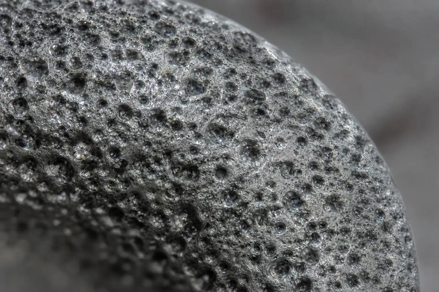
- EDM marks: Random crater pattern (like orange peel), no directional tool marks, uniform texture across all surfaces regardless of geometry.
- CNC marks: Parallel cusp marks (toolpath scallops), directional pattern changes with surface orientation, smooth corners with visible radius.
- Polished EDM: Smooth surface with occasional residual crater marks visible under 10x magnification?? sign of cost-effective EDM followed by light polishing.
Frequently Asked Questions
How accurate is sinker EDM for mold making?
Sinker EDM routinely achieves positional accuracy of ?0.005 mm and dimensional accuracy of ?0.01 mm on modern machines with closed-loop servo control. For finishing operations with orbital motion and well-designed electrodes, tolerances of ?0.005 mm are achievable. The limiting factors are electrode machining accuracy, thermal stability during the burn cycle, and flushing consistency. Wire EDM is even more accurate (?0.002 mm), but sinker EDM accuracy is more than sufficient for virtually all injection mold cavity requirements.
Why is graphite preferred over copper for electrodes?
Graphite dominates mold-making EDM for three primary reasons. First, graphite machines significantly faster than copper??igh-speed CNC milling with diamond-coated carbide tools can produce complex graphite electrodes in hours rather than days. Second, graphite has a wear ratio below 0.1% under proper settings, meaning electrode geometry stays intact through hundreds of burns. Third, graphite has negligible thermal expansion compared to copper, so electrode dimensions remain stable during long burn cycles. Copper is reserved for applications requiring the absolute best surface finish (VDI 6-8) where its higher wear rate is acceptable for a single finishing pass.
Does EDM weaken the mold steel?
EDM does not weaken the bulk mold steel, but it does create a thin recast layer (typically 1-30 microns depending on settings) with altered metallurgical properties. This layer is harder and more brittle than the base steel and contains micro-cracks from rapid quenching. For most injection mold applications, the recast layer is removed through post-EDM polishing, abrasive flow machining, or chemical etching. For critical high-pressure or high-cycle molds, stress-relief heat treatment after EDM is recommended. When properly post-processed, EDM-produced cavities have fatigue life comparable to conventionally machined cavities.
What surface finish can sinker EDM achieve without polishing?
Without polishing, sinker EDM can achieve surface finishes ranging from VDI 45-52 (rough, approximately Ra 12-18 microns) down to VDI 6-12 (mirror-like, approximately Ra 0.4-1.6 microns). The finest finishes require low-energy finishing passes with copper electrodes and extended cycle times. A practical production finish without polishing is typically VDI 18-24 (Ra 1.6-3.2 microns) using graphite electrodes and optimized finishing parameters. For mirror finishes below VDI 12, post-EDM polishing is almost always more economical than extended EDM cycle time.