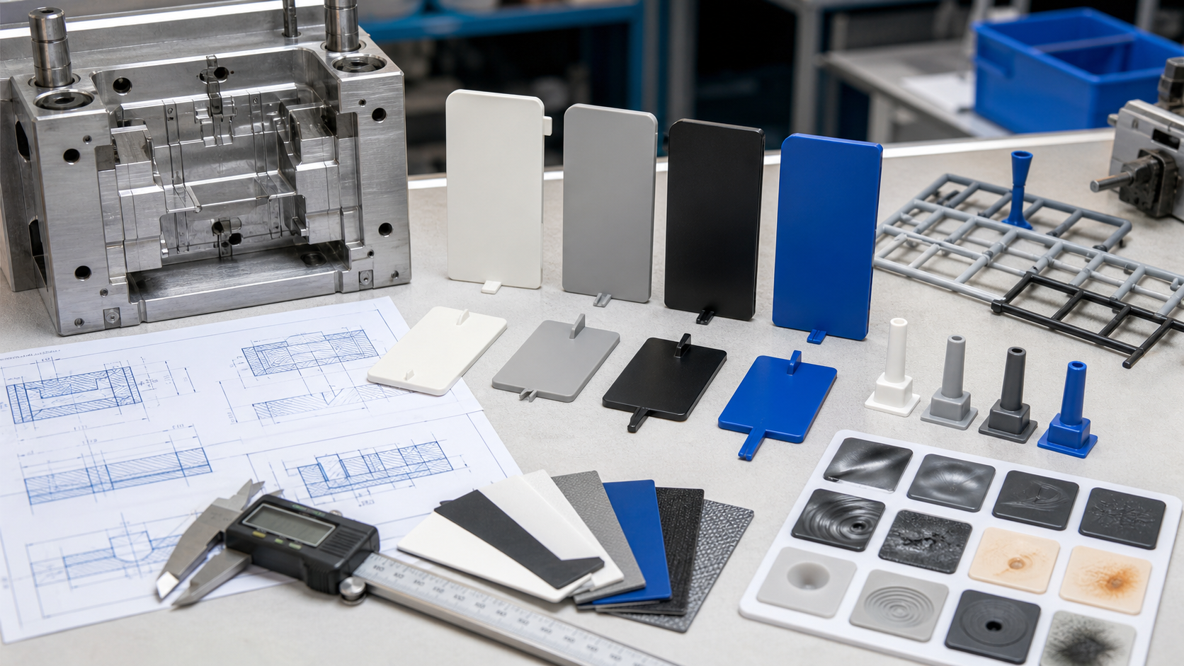
Runner and sprue design for injection molding must deliver a stable melt temperature and pressure to every cavity while controlling pressure loss, shear, scrap, release and regrind. A runner that fills one cavity earlier than another can create different packing, shrinkage, weld lines, dimensions and cosmetics even when the machine settings are identical.
For a buyer, the useful review is not only runner diameter. It includes resin rheology, shot size, cavity layout, flow balance, gate connection, sprue release, cold-slug management, regrind policy, cycle target and tool-life requirements. The mold-flow or DFM package should explain how the runner system will be balanced and how cavity-to-cavity evidence will be collected during trials.
The engineering function of runners and sprues
| Design objective | What it controls | Evidence to review | Risk when overlooked |
|---|---|---|---|
| Balanced delivery | Pressure, temperature and fill timing at each cavity | Runner layout, short shots, cavity weight and pressure | Unequal fill, packing, shrinkage and cycle response |
| Controlled pressure loss | Machine pressure, fill time and usable process window | Flow length, section, viscosity and pressure trace | Short shots, high pressure, flash or an oversized runner |
| Thermal stability | Freeze-off, shear heating and material residence time | Runner section, melt temperature and cycle | Cold slug, degradation, stringing or inconsistent gates |
| Scrap and release | Runner weight, separation, sprue pull and regrind | Runner mass, sprue bush, cold slug and automation | Excess scrap, stuck runner or unstable regrind condition |
| Maintainability | Wear, polish, venting, insert repair and cleaning | Steel, access, runner insert and tool-life plan | Drift, flash, imbalance or expensive repair |
Use the gate design guide to connect runner delivery with gate type and location. The hot-runner versus cold-runner guide is for system selection, while this page focuses on cold-runner geometry, sprue sizing, pressure and cavity balance.
The mold design and mold making page explains how runner decisions fit into the complete tooling review.
Inputs that control runner geometry
Start with the resin’s viscosity, melt range, filler, shear sensitivity and shrinkage. High-viscosity or filled grades may need a larger or more direct path, while shear-sensitive or high-temperature materials need attention to residence time and local heating. Shot size should be reviewed against the machine barrel and runner volume so the material does not remain in the system too long.
Map cavity positions, gate locations, projected area, part weight, flow length, wall thickness and expected end-of-fill. A geometrically equal runner is not always rheologically balanced when cavities have different flow resistance. The runner may need natural balance, engineered balance or a different gate arrangement. Include regrind policy because cold-runner scrap can affect material history, color and performance.
- Resin grade, viscosity, filler, melt range, shrinkage and regrind limit.
- Part weight, cavity count, gate position, flow length and wall thickness.
- Machine size, screw diameter, shot utilization, pressure limit and cycle.
- Runner section, length, taper, intersections, cold-slug wells and sprue.
- Automation, runner separation, scrap handling and mold maintenance access.
- Critical dimensions, cosmetics, weld-line limits and cavity-specific acceptance.
Geometry and balance rules
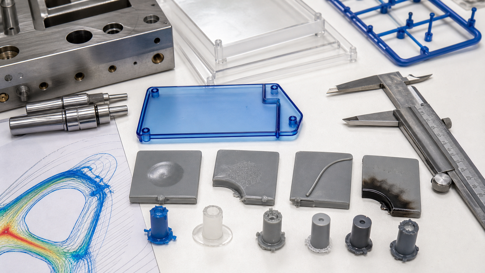
A full-round runner can provide a favorable flow-to-volume relationship when machined accurately in both mold halves. Trapezoidal or modified sections may simplify machining or release, but the section and surface must be consistent enough to avoid unnecessary pressure loss. The runner should taper toward the gate where appropriate, maintain supported transitions and avoid sharp corners that increase dead spots or shear.
Natural balance uses equal flow lengths and similar resistance. Engineered balance adjusts runner dimensions to compensate for different cavity or gate resistance. Both should be verified with short shots and cavity-specific weight, not accepted only from CAD symmetry. A cavity that fills early may receive more packing and have different dimensions even if all gates look identical.
The sprue should release reliably from the sprue bush and should not create an oversized thermal mass that extends cooling or causes stringing. A cold-slug well can capture the colder material at the front of the sprue or runner. Runner intersections should be smooth and supported, and the system should leave enough steel for strength, cooling and maintenance.
Material and production-volume effects
| Material condition | Runner concern | Design response | Validation focus |
|---|---|---|---|
| High-viscosity resin | Higher pressure loss and earlier freeze-off | Review section, flow length, melt condition and gate connection | Peak pressure, fill time and cavity balance |
| Filled resin | Shear, fiber breakage, wear and directional shrinkage | Use suitable steel, smooth transitions and controlled shear | Pressure, fiber orientation, wear and dimensions |
| Shear-sensitive resin | Local heating, degradation and color change | Avoid restrictive corners, excessive residence and unnecessary length | Melt condition, purge, odor, color and surface |
| High-volume tool | Wear and temperature drift change balance over time | Provide access, inspection and maintenance limits | Long-run weight, pressure and flash trend |
| High scrap/regrind | Runner mass affects material history and cost | Review hot/cold choice, separation, regrind and quality controls | Scrap ratio, lot traceability and part performance |
Tooling options and cost trade-offs
| Option | Benefit | Trade-off | Suitable when |
|---|---|---|---|
| Full-round cold runner | Good flow efficiency and familiar machining | Needs accurate alignment and creates runner scrap | General multi-cavity production |
| Trapezoid/modified runner | Can simplify one-side machining or release | Different flow efficiency and surface condition | Tool geometry or maintenance favors the section |
| Engineered balance | Compensates for unequal cavity resistance | Needs analysis and trial evidence | Different part weights, gates or flow lengths |
| Cold-slug well | Captures colder material before the gate | Uses space and adds runner volume | Cold-start or material-front risk exists |
| Replaceable runner insert | Supports repair, wear or special steel | Insert fit, cost and witness control | Filled resin, high wear or high-value tool |
Failure modes and corrective actions
Unbalanced filling may come from unequal flow resistance, gate restriction, temperature variation, a blocked vent or a runner dimension that is not actually balanced. Freeze-off can appear as a short shot, low weight or a cavity that stops receiving pack. Shear heating may create burns, color drift, odor or degradation. Stringing and sprue pull can come from geometry, temperature, release, gate or cycle conditions.
Corrective action should compare short shots, cavity weight, pressure, gate seal, runner condition and material history. Enlarging every runner can increase scrap and reduce control without fixing the actual restriction. A cavity-specific insert, gate change, vent repair, runner transition or process adjustment may be more appropriate. Keep the approved runner and cavity data with the mold maintenance record.
Validation at mold trial and production approval
- DFM review: confirm cavity layout, runner path, gate, sprue, cold slug, cooling and ejection.
- Short-shot balance: compare fill percentage and flow front by cavity before full packing.
- Pressure/weight check: record peak pressure, transfer, part weight and cavity variation.
- Runner inspection: check release, stringing, cold slug, surface, separation and sprue condition.
- Cycle study: include runner cooling and separation in the production cycle.
- Long-run approval: compare consecutive shots, material lots, cavities and scrap/regrind records.
DFM checklist and RFQ data package
- Provide CAD, drawing, resin, grade, texture, annual volume and tool-life target.
- State cavity count, part weight, gate concept, machine, shot utilization and cycle.
- Define runner scrap, regrind allowance, color changes and cleanliness limits.
- Request runner/sprue section, balance method, cold-slug, release and maintenance plan.
- Ask for short-shot, pressure, cavity-weight, runner-separation and cycle evidence.
- Define cavity-specific dimensional, cosmetic and functional acceptance.
For an RFQ, include the controlled CAD, drawing, resin and grade, cavity target, annual volume, regrind policy, machine constraints and runner-scrap expectation. We can then compare cold-runner geometry and cavity balance against pressure, material history, cycle and production cost.
Include the expected maintenance interval and the method used to confirm runner dimensions after polishing or repair. This prevents a balanced first trial from drifting silently during production.
Runner and Sprue Decisions Before Steel Release
| Decision | Risk If It Is Vague | Evidence to Confirm |
|---|---|---|
| Runner balance | Cavities fill and pack at different times | Short-shot sequence, cavity weights, fill time and pressure evidence |
| Runner and sprue size | Pressure loss, excessive shear, long freeze or unnecessary scrap | Material viscosity, shot size, cycle target and gate-seal behavior |
| Cold or hot runner route | Tool cost, maintenance, color change, valve timing or regrind plan is underestimated | Annual volume, resin, color, gate requirements and service plan |
| Fiber-filled nylon | Orientation, wear and cavity imbalance are treated like unfilled resin | Exact PA grade, filler level, flow direction and tool-maintenance limits |
A runner can be geometrically symmetric and still fill unevenly when gates, inserts, cooling, venting, temperature, or material viscosity differ. Validate the actual production-intent mold and resin instead of approving only a CAD layout.
How Nylon Plastic Supports the Project
Nylon Plastic has supported material selection and finished plastic-part manufacturing since 2005. For runner and sprue design for injection molded plastic parts, the useful review connects the drawing, material, tooling or machining route, inspection state, and production plan before a quote is approved.
- Review unfilled PA, PA-GF20, and PA-CF30 with the intended gate, flow direction, drying state, and cavity arrangement.
- Connect runner design to mold fabrication, cavity balance, sampling, scrap control, and the acceptance data required for release.
- Define annual volume, color changes, regrind policy, gate vestige, maintenance, and mold ownership in the RFQ.
Related Reading
Frequently Asked Questions
What is the purpose of an injection molding runner?
The runner carries the melt from the sprue to one or more gates while controlling pressure loss, temperature, filling balance, scrap, separation, and packing access.
How is runner balance checked?
Use short shots, cavity weights, fill time, pressure or cavity data where available, gate-seal behavior, and repeated samples from every cavity under production-intent conditions.
Do glass-filled nylon grades change runner design?
They can. Viscosity, fiber orientation, shear, tool wear, gate restriction, and cavity balance should be checked for the exact PA-GF grade rather than copied from unfilled nylon.
What should a runner and sprue RFQ include?
Include the part and mold files, resin and filler, cavity count, annual volume, color changes, gate requirements, cycle target, regrind policy, inspection plan, and mold ownership terms.
Request a Runner and Sprue Design Review
Send the part, mold concept, resin, cavity target, annual volume, and gate requirements for a balanced filling and tooling review.