
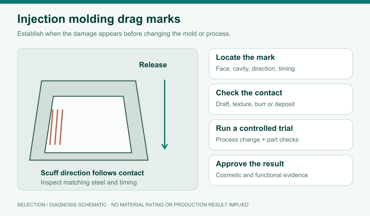
Injection molding drag marks are surface scuffs or scratches associated with contact as a part releases from the tool. Before changing molding settings, establish where the mark appears, which way the part moves and whether the damage exists before handling. A photograph alone may not distinguish a release problem from a flow pattern or an assembly scratch.
Confirm when the damage appears
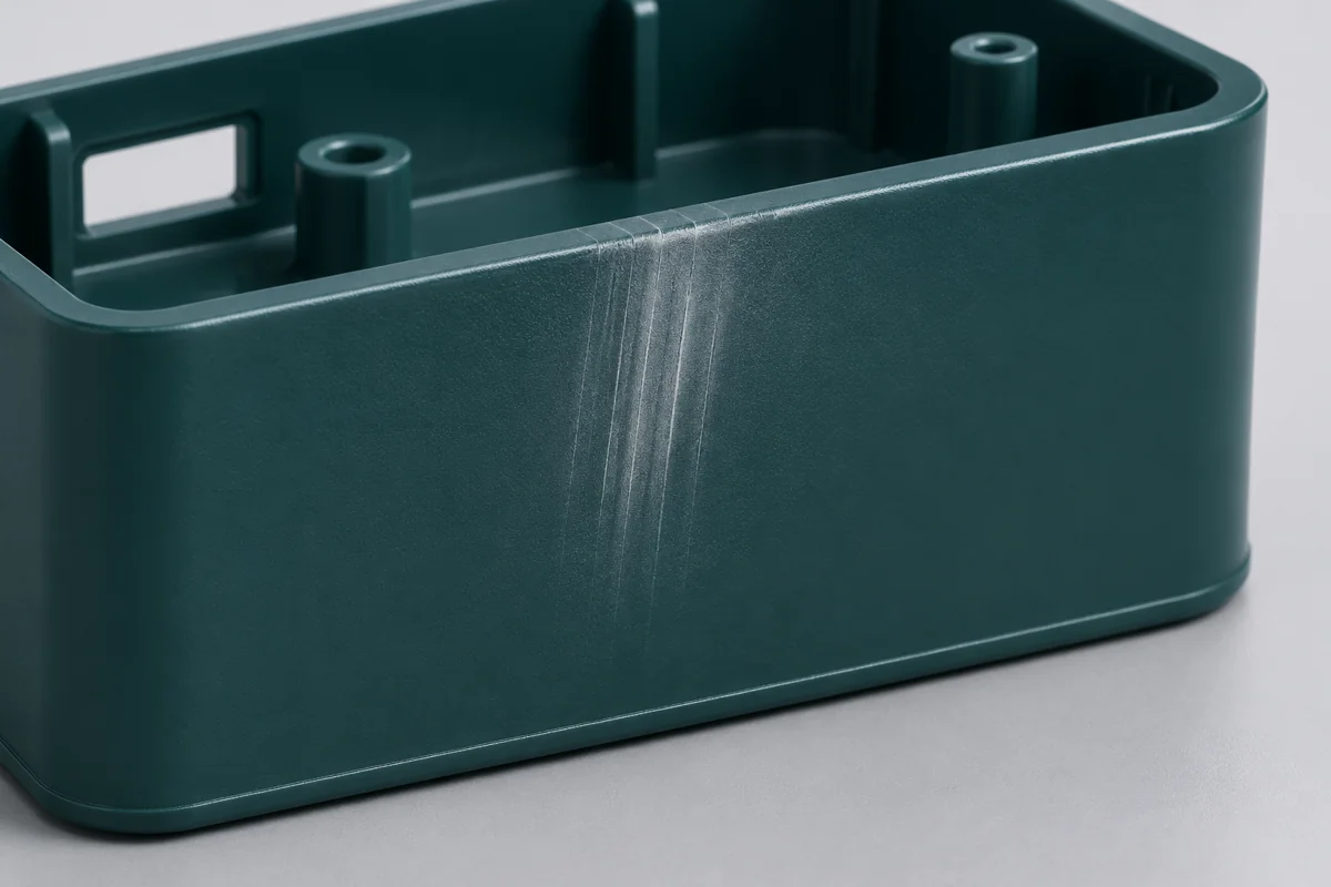
Collect an untouched sample and identify its cavity, orientation and draw direction. Compare it with parts after removal, trimming, packing and assembly. Record whether the same face and location are affected repeatedly. These observations help the molding team decide whether to investigate tool release or a later handling step.
Ask for a close photograph with a scale and a wider view that locates the mark on the part. If the mark is difficult to see, use a consistent light direction for good and rejected samples. Avoid comparing a glossy sample in direct light with a textured sample photographed from another angle.
Keep this record with the drawing revision, material grade, color and approved surface reference. A location described only as “the scratched side” is hard to trace when the sample changes hands.
Separate drag marks from other surface defects
| Observation | First question | Evidence to compare |
|---|---|---|
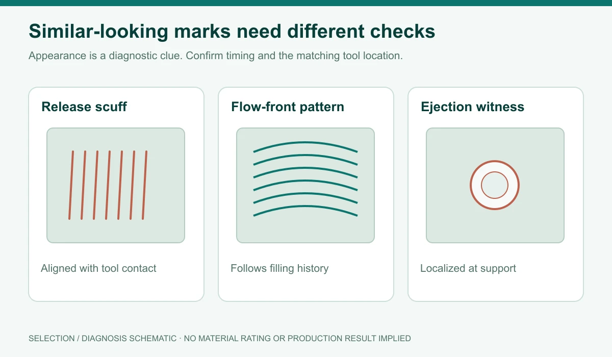
| Lines aligned with release or side-action movement | Does the path match contact with a tool surface? | Part orientation, matching steel location and sequence of motion. |
| Waves or bands following the filling pattern | Was the pattern formed as the material flowed? | Gate location and filling history; see the flow-mark guide. |
| Whitening, indentation or a raised witness near an ejector | Is local support or release force involved? | Ejector layout, part support and the condition at removal. |
| Random scratches appearing after removal | Do handling, trimming, packing or assembly introduce contact? | Samples retained at each stage and contact points in the downstream process. |
The patterns above are clues, not a final root-cause diagnosis. Toray’s AMILAN troubleshooting guide treats flow marks and other molding defects separately. For filling-related patterns, use the flow marks versus jetting guide rather than applying a demolding fix to every streak.
Check draft, surface condition and release motion
Review the draw direction against the affected wall, rib, boss or side-action face. The draft-angle guide explains how wall depth, texture and release direction belong in the same review. Do not apply a single draft rule to every resin and surface.
Inspect the corresponding tool area for a burr, damage, deposits, unintended undercut or surface finish that resists release. Confirm whether a slide or lifter clears the part in the intended sequence. The ejection-design guide covers the relationship between part support and the release system.
Material-specific guides can point in different directions. Celanese’s LDPE/EVA guide associates part sticking and drag marks with mold design and friction. Covestro’s TPU troubleshooting guide also distinguishes linear surface damage during release. Those publications concern their stated materials; their settings are not universal recipes for nylon, PBT or another compound.
Review the process without hiding a tool problem
Ask the molding team to retain the baseline process record before a trial. Where the part, grade and machine permit it, compare one defined change with the baseline and record the result. Changes to packing, cooling or release motion can affect dimensions, sink, warpage and cycle behavior as well as appearance.
A lower reject count after a settings change does not establish that the process has a useful operating window. Check repeat samples, the affected cavities and critical dimensions. If a proposed change needs an unacceptable dimensional shift to release the part, the tool or part design may still need review.
Do not treat extra mold-release agent as an automatic production fix. Identify the proposed product and its compatibility with the resin, painting, bonding, printing and other downstream requirements before considering it. Keep any change to the approved formulation or surface treatment visible to the customer.
A corrective trial needs a record the buyer can review
Locate
Identify the cavity, part face, draw direction and the stage at which the mark first appears.
Explain
State the suspected contact or process mechanism and what observation would support or reject it.
Compare
Record the approved trial change and retain comparable baseline and trial samples.
Accept
Check appearance, critical dimensions and functional fit against the agreed criteria.
Before polishing or reworking steel, define who approves the change and how it affects texture, dimensions and future maintenance. A cosmetic improvement should not silently change a sealing face, bearing fit or customer-approved surface.
For a recurring issue, request the change record, sample identification and the evidence supporting repeat production. A message saying “adjusted the machine” is insufficient to reproduce the corrective action after a material lot, operator or tool-maintenance change.
Agree what counts as an acceptable surface
Specify the visible area and its importance: a hidden internal wall, a user-facing cover and a sealing surface may need different acceptance criteria. Define viewing conditions and an approved reference sample where appearance matters. Do not replace a drawing requirement with an unrecorded verbal acceptance.
For functional surfaces, decide whether the mark requires a fit, sealing, retention or other relevant check. The plastic-part quality inspection guide helps connect sample approval to the drawing and inspection record. Appearance alone does not establish functional acceptability.
What to send with a drag-mark inquiry
- Part drawing and revision, plus the affected surface marked on a photograph.
- Exact resin grade, color and reinforcement, and any recent approved material change.
- Good and rejected samples identified by cavity and production stage.
- Draw direction, gate and ejector locations, texture reference and available tool history.
- Current process record, previous trial changes and their measured effects.
- Quantity, functional requirements and the appearance criteria that must be met.
For a new part, use the injection molding service page to review the broader manufacturing requirements. For an existing defect, explain whether the request concerns part design, material selection, tool review or replacement production so the scope can be assessed.
Injection molding drag marks FAQ
Are all scratches drag marks?
No. Confirm the stage at which the scratch appears and whether its direction corresponds to tool contact. Handling and assembly can introduce similar damage after molding.
Will increasing draft always solve the problem?
No. Draft may be relevant, but burrs, deposits, texture, retention and release motion also need checking. Any geometry change must preserve the required dimensions and function.
Can I accept parts once the mark is less visible?
Compare the samples with the agreed cosmetic reference and relevant dimensional or functional requirements. A less visible mark does not by itself approve a sealing or mating surface.
Should the tool be polished before a process trial?
First record the baseline and identify the suspected cause. The appropriate order depends on the defect and tool condition; obtain approval before steel changes that affect dimensions or texture.