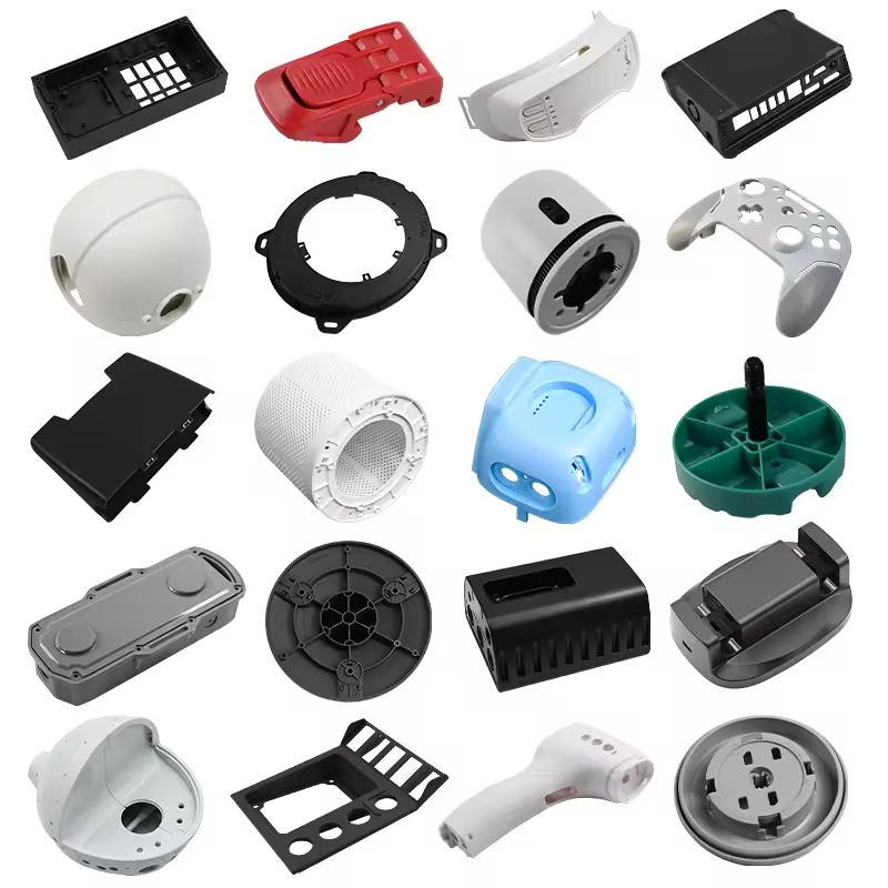
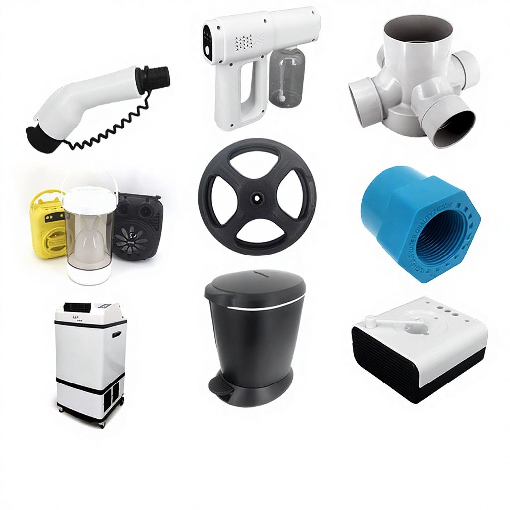
Plastic injection molding parts are ubiquitous in modern life, found in everything from automotive dashboards and medical devices to consumer electronics and household appliances. Injection molding is the most widely used process for mass‑producing complex, high‑precision plastic components because it offers exceptional repeatability, design flexibility, and cost‑efficiency at scale. This guide covers the materials, process, applications, and quality considerations for custom injection molded parts, helping you understand how to bring your design to production reliably and affordably. Nylon Plastic reviews drawings, material requirements, tooling constraints, inspection needs and production quantities for custom plastic-part enquiries.
Scope: This guide focuses on part design, material, process control and acceptance questions. For a commercial DFM, tooling and production review, use our plastic injection molding services.
What Is Injection Molding?
Injection molding is a manufacturing process in which molten thermoplastic or thermoset material is forced under high pressure into a precisely machined metal mold cavity. The material cools and solidifies into the shape of the cavity, forming a finished part. Once the mold is closed, the cycle repeats, enabling the production of thousands to millions of identical parts with minimal variation.
Cycle and tolerance capability depend on the resin, geometry, mold, machine, process window and inspection method. A ±0.05 mm target can be a useful review point, but it is not a universal guarantee and must be evaluated against the drawing. It is ideal for high‑volume production runs but can also be cost‑effective for smaller quantities when using rapid tooling or multi‑cavity molds.

Why Choose Injection Molding for Your Plastic Parts?
Injection molding offers several distinct advantages over other manufacturing methods like 3D printing, CNC machining, or thermoforming.
| Advantage | Description |
|---|---|
| High Volume Efficiency | Once the mold is built, cycle times are very short (often under 60 seconds), making it the most economical process for large quantities. |
| Exceptional Precision & Repeatability | Modern injection molding machines and hardened steel molds produce identical parts within tight tolerances, critical for assembly‑line fit and functional performance. |
| Complex Geometries | Undercuts, threads, ribs, bosses, and complex internal features can be molded directly, eliminating secondary operations. |
| Wide Material Choice | Dozens of thermoplastics—from commodity resins like PP and ABS to engineering plastics like PA, PC, PBT, and high‑performance polymers like PEEK—are readily available. |
| Low Per‑Part Cost | The high upfront tooling cost is amortized over the production volume, making per‑part cost extremely low for large runs. |
| Integration of Features | Insert molding, overmolding, and multi‑shot molding allow the integration of metal inserts, soft‑touch grips, or different colors in one part. |
| Excellent Surface Finish | Mold textures (from matte to high gloss) can be applied directly to the tool, producing parts ready for use without post‑processing. |
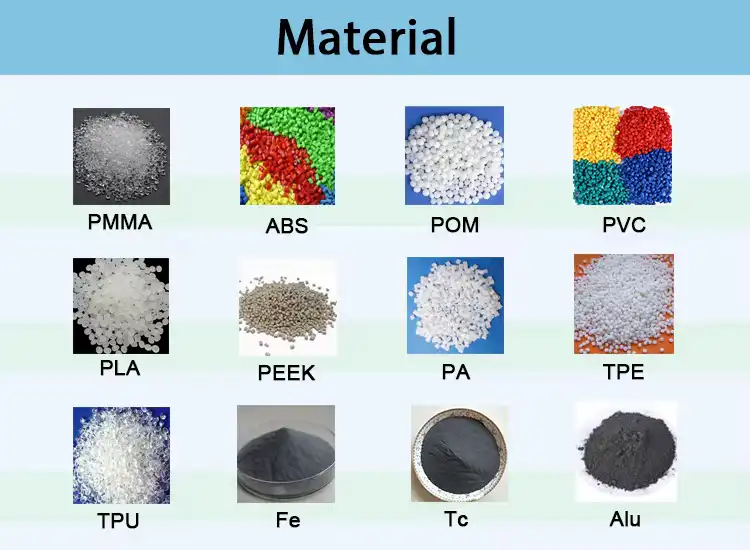
Common Materials for Plastic Injection Molding Parts
Selecting the right material is critical for part performance, cost, and manufacturability. The table below summarizes the most commonly used thermoplastics in injection molding.
| Material | Key Properties | Typical Applications |
|---|---|---|
| ABS (Acrylonitrile Butadiene Styrene) | High impact strength, toughness, good heat stability, excellent surface finish, easy to plate or paint | Automotive interior trim, dashboard components, grilles, mirror housings, consumer electronics enclosures, toys, power tool housings, medical device enclosures |
| PP (Polypropylene) | Lightweight, excellent chemical resistance, fatigue resistance (living hinge), low cost, good electrical insulation | Automotive battery cases and trims, consumer goods, food containers, caps and closures, medical syringes, industrial pipes and fittings |
| PA6 / PA66 (Nylon) | High strength, wear resistance, self‑lubricating, good fatigue resistance, absorbs moisture | Gears, bearings, bushings, automotive under‑hood components (engine covers, intake manifolds), electrical connectors, cable ties |
| PC (Polycarbonate) | High impact strength, optical clarity, heat resistance, dimensional stability | Transparent covers, headlamp lenses, medical devices, electronic enclosures, safety goggles, bullet‑resistant glass substitutes |
| PBT (Polybutylene Terephthalate) | Good electrical properties, chemical resistance, dimensional stability, often glass‑reinforced | Electrical connectors, sensor housings, ignition components, exterior automotive trim, appliance parts |
| POM (Acetal) | High stiffness, low friction, excellent wear resistance, good dimensional stability | Gears, bearings, valve components, pump parts, food handling equipment, zippers |
| TPU (Thermoplastic Polyurethane) | Flexibility, abrasion resistance, shock absorption, rubber‑like feel | Seals, gaskets, overmolded soft‑grip handles, protective bumpers, shock‑absorbing components |
| PC/ABS Blend | Balanced properties of PC and ABS: high impact resistance, heat resistance, good processability | Automotive interior parts (instrument panels, pillar covers), electronic housings, medical equipment enclosures |
For help selecting the optimal material for your injection molding project, visit our material selection hub .

The Injection Molding Process: Step by Step
A professional injection molding service follows a rigorous workflow to ensure part quality and consistency.
| Stage | Core Activities | Outcome |
|---|---|---|
| 1. Part Design & DFM | Design the part using CAD software. Engineers perform Design for Manufacturability (DFM) analysis to optimize wall thickness, draft angles, gate location, and ejection features. | A production‑ready design with minimal risk of defects. |
| 2. Material Selection | Choose the appropriate thermoplastic based on mechanical, thermal, chemical, and aesthetic requirements. | Guaranteed material performance for the application. |
| 3. Mold Design & Fabrication | Design a multi‑part steel mold (e.g., P20, 718, NAK80, S136) using advanced CAD/CAM. Machine the mold with high‑precision CNC, then assemble and polish. | A durable, high‑precision tool capable of millions of cycles. |
| 4. Injection Molding | Install the mold in an injection molding machine. Melt plastic pellets, inject into the cavity under high pressure, hold pressure, cool, and eject the part. | Consistent, repeatable parts meeting dimensional specifications. |
| 5. Secondary Operations (if needed) | Perform trimming, degating, drilling, tapping, ultrasonic welding, heat staking, painting, plating, or assembly. | Finished parts ready for integration or shipment. |
| 6. Quality Assurance | Inspect parts using CMM, optical comparators, and other tools. Test for dimensions, strength, and appearance. | Inspection results and records matched to applicable customer or regulatory requirements. |

Key Design Considerations for Injection Molded Parts
To ensure your plastic injection molding parts are manufacturable, cost‑effective, and defect‑free, adhere to these design guidelines:
| Design Feature | Recommended Practice |
|---|---|
| Wall Thickness | Keep as uniform as possible. Typical range: 1.5–4.0 mm for most thermoplastics. Avoid thick sections that cause sink marks and voids. |
| Draft Angle | Add 1–3° of draft to all vertical walls to allow easy part ejection without scratching. |
| Ribs | Use ribs to add stiffness instead of increasing wall thickness. Rib thickness should be ≤ 0.6 times the nominal wall. |
| Corners | Round internal and external corners with a radius ≥ 0.5 mm to reduce stress concentration and improve flow. |
| Gates | Locate gates away from stress‑bearing areas and aesthetic surfaces. Common types: edge, fan, pin, or submarine gates. |
| Ejector Pins | Design flat areas for ejector pins; avoid deep undercuts that require side‑actions (increase mold cost). |
| Surface Finish | Specify the desired finish (e.g., SPI standards: glossy, semi‑gloss, matte, textured). Textures can hide minor defects. |

Applications of Plastic Injection Molding Parts Across Industries
Injection molded components serve virtually every sector. Below are key examples.
| Industry | Typical Parts | Material Examples | Critical Requirements |
|---|---|---|---|
| Automotive | Dashboard trim, door handles, HVAC vents, connector housings, under‑hood covers | ABS, PP, PA66, PC/ABS | Heat resistance, impact strength, UV stability, tight tolerances |
| Medical & Healthcare | Syringe barrels, IV connectors, diagnostic device housings, surgical instrument handles | PC, ABS, PA, PP | Biocompatibility, sterilizability (EtO, gamma), cleanability, precision |
| Consumer Electronics | Smartphone cases, laptop bezels, power tool housings, TV frames | ABS, PC, PC/ABS | Aesthetic surface finish, flame retardancy (UL94 V‑0), dimensional stability |
| Home Appliances | Washing machine agitators, refrigerator door bins, blender jugs, vacuum cleaner parts | PP, ABS, PA | Chemical resistance, toughness, thermal stability, food contact (FDA) grades |
| Industrial Equipment | Gears, pump housings, valve bodies, conveyor chain links, bearing retainers | POM, PA66, PBT, PEEK | Wear resistance, low friction, high strength, chemical resistance |
| Packaging | Caps, closures, thin‑walled containers, crates | PP, HDPE, PET | Fast cycling, good flow, stiffness, barrier properties |

Wear‑Resistant and Mechanical Plastic Parts
For applications requiring exceptional durability, such as mechanical plastic special‑shaped parts or components exposed to continuous friction, material selection is critical. Glass‑fiber‑reinforced grades (e.g., PA66‑GF30, PBT‑GF30) offer significantly improved stiffness, heat deflection temperature, and creep resistance. For high‑wear environments, acetal (POM) provides a low coefficient of friction and excellent wear resistance, making it ideal for gears and bearings.
TPU (thermoplastic polyurethane) grades, such as ETERNALAST® LS7093A, offer excellent abrasion resistance (29 mm³) and high tear strength (131 kgf/cm) with a compression set of just 15% after 22 hours at 70°C, making them suitable for injection‑molded technical parts, cleaning devices, sporting goods components, and chair casters.
PP + GF30 (30% glass fiber) combines the chemical resistance and low density of polypropylene with significantly enhanced mechanical properties. It is widely used for structural components that must resist deformation under load, such as automotive brackets and industrial housings.

Quality Assurance for Injection Molding Parts
When a project requires ISO 9001, IATF 16949 or ISO 13485 controls, verify the certificate holder, facility, scope, standard version and expiration before approval. The part control plan should then define:
- First Article Inspection (FAI): Comprehensive measurement of the first production run to verify all dimensions against the CAD model.
- In‑Process Monitoring: Continuous monitoring of melt temperature, injection pressure, holding pressure, and cooling time.
- Dimensional Inspection: Use of Coordinate Measuring Machines (CMM), optical comparators, and handheld gauges.
- Visual Inspection: Checking for surface defects such as sink marks, flow lines, burns, and short shots.
- Material Certification: Traceable material certificates from the resin supplier.
- Functional Testing: Where required, tests for impact resistance, heat deflection, tensile strength, or chemical resistance.

Customization Options for Injection Molded Parts
We offer a wide range of customization to meet your exact specifications:
| Customization | Options |
|---|---|
| Material | ABS, PP, PA6, PA66, PC, PBT, POM, TPU, PEEK, and custom blends |
| Color | Pantone, RAL, or custom matching. See our color customization services. |
| Surface Finish | Polished (high gloss), matte, textured (e.g., grain, leather, sand), plated, painted |
| Logo & Marking | Molded‑in text, logos, part numbers, or laser engraving |
| Assembly | Ultrasonic welding, heat staking, snap‑fits, screw assembly, adhesive bonding |
| Packaging | Bulk boxes, custom foam inserts, retail‑ready packaging |
How to Prepare an Injection Molding Parts RFQ
Nylon Plastic can review the drawing, material requirements, tooling route, inspection plan and expected volume for a custom-part enquiry. Any required certification, facility scope and production record should be listed in the RFQ and verified before supplier approval.
- Material: State manufacturer and grade when fixed, plus color, reinforcement, conditioning and approved substitutes.
- Tooling: Define tool ownership, cavity strategy, expected life, change control and maintenance responsibilities.
- Quantity: Separate prototype, pilot, annual and lifetime volume instead of assuming a universal MOQ.
- Quality: Mark critical dimensions, cosmetic zones, inspection methods, sample size and required records.
- Commercial controls: Agree NDA, file access, revision control, packaging and shipping responsibilities.
Conclusion: Approving Plastic Injection Molding Parts
Plastic injection molding parts should be approved against the controlled drawing, resin grade, cavity, conditioning state, inspection method and functional test. Use the checklist above to compare supplier responses before releasing tooling or production.
Prepare the RFQ: Send the controlled CAD and drawing, resin requirements, annual and lifetime volume, critical dimensions, appearance limits and required records.
FAQ
What information is needed to quote injection molded parts?
Send the controlled CAD and drawing, resin requirement, expected quantity, critical dimensions, appearance limits, assembly conditions and required inspection records. Identify the revision and intended use so the quote can separate assumptions from confirmed requirements.
How should production quantity be specified?
State prototype, pilot, annual and lifetime volume separately. The supplier can then propose a tool material, cavity count, maintenance plan and minimum run for the actual program instead of applying a fixed MOQ to every part.
How are critical dimensions and inspection requirements defined?
Mark functional dimensions and datums on the drawing, then agree the conditioning state, measurement method, fixture, sample size and acceptance record. A generic tolerance should not replace a drawing-specific review.
When should inserts or overmolding be discussed?
Identify inserts, substrate materials, locating features, bond requirements, cosmetic zones and pull-out or peel tests before tool design. The interface, handling method and validation sample plan should be part of the quotation.
How should certifications and regulated requirements be verified?
List the required standard and records in the RFQ. Before approval, verify the certificate holder, facility, scope, standard version and expiration, then confirm that the proposed material and process are covered.