
Injection molding is the dominant manufacturing process for plastic parts at scale. It converts raw polymer pellets into finished components in seconds, producing everything from bottle caps to automotive dashboards with high precision and repeatability. Understanding how the process works helps engineers design better parts, avoid common defects, and communicate effectively with molders.
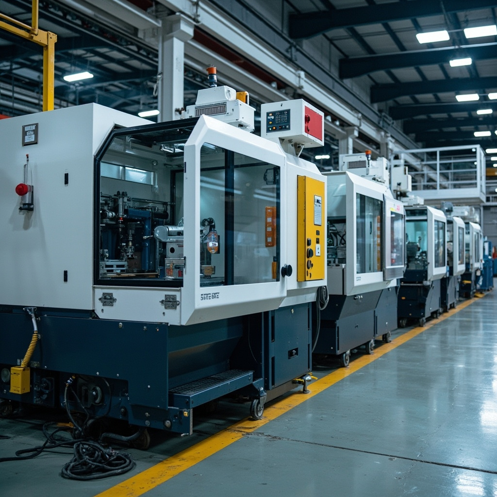
How Injection Molding Works: The Basic Cycle
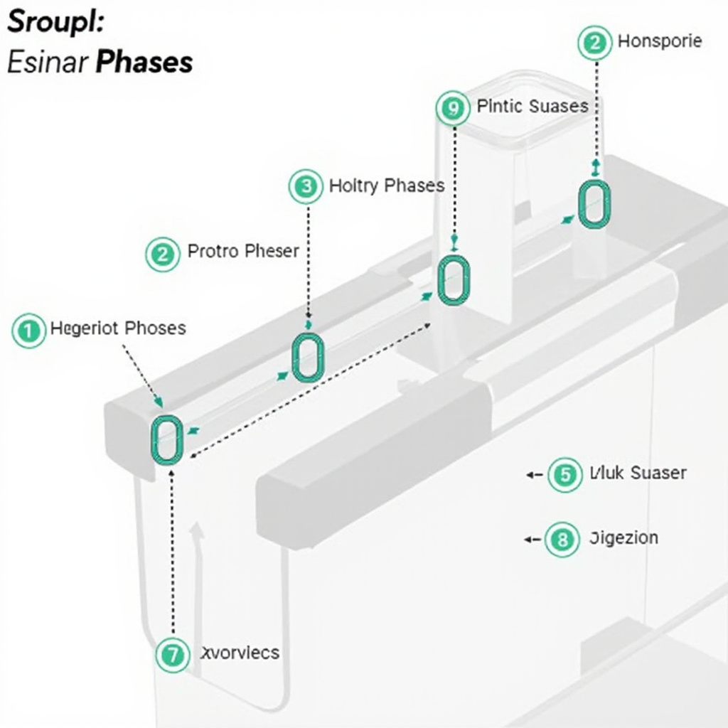
The injection molding cycle consists of five distinct phases, each with specific parameter controls that determine part quality.
1. Clamping
Before injection begins, the mold must be securely clamped shut. The clamping force must exceed the injection pressure (typically 60-150 MPa) to prevent flash—thin layers of material escaping the mold cavity at the parting line. Clamp tonnage is typically calculated at 3-8 tons per square inch of projected part area, depending on material and part geometry.
2. Injection
Plastic pellets are fed from a hopper into a heated barrel where a rotating screw melts and homogenizes the material. The molten plastic is then injected into the mold cavity at high speed and pressure. Injection speed and pressure profiles are critical—they must fill the cavity completely before the material begins to solidify.
3. Packing and Holding
After the cavity is filled, additional pressure (holding pressure) is applied to compensate for material shrinkage as the part cools. This phase typically lasts 5-20 seconds depending on wall thickness. Inadequate holding pressure results in sink marks and dimensional shortfalls.
4. Cooling
The part solidifies as heat transfers to the mold walls. Cooling time is the longest phase of the cycle, typically 10-60 seconds. Cooling channel design in the mold is critical—well-designed cooling reduces cycle time and improves part quality.
5. Ejection
Once the part has solidified sufficiently, the mold opens and an ejection system (typically spring-loaded pins or a stripper plate) pushes the part out of the cavity. Draft angles on part walls facilitate ejection. Ejection too early causes warpage; too late wastes cycle time.
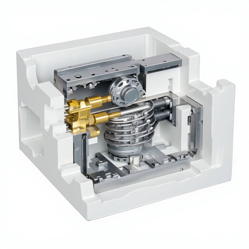
Key Process Parameters
| Parameter | Typical Range | Effect on Part |
|---|---|---|
| Melt Temperature | 220-300 degrees C (material dependent) | Higher = better fill, more degradation risk |
| Mold Temperature | 20-120 degrees C | Higher = better surface, longer cycle |
| Injection Pressure | 60-150 MPa | Higher = better fill, flash risk |
| Holding Pressure | 40-80% of injection pressure | Compensates shrinkage, affects density |
| Cooling Time | 10-60 seconds | Longer = less warpage, slower cycle |
 id #ddd;”>Total Cycle Time |
15-120 seconds (typical) | Drives production cost per part |
Common Defects and Their Causes
Sink Marks
Dimensional voids or depressions on the surface, typically over thick sections or ribs. Caused by insufficient holding pressure, short holding time, or excessive melt temperature. Fix: increase packing pressure and time, reduce wall thickness transitions.
Flash
Thin excess material at the parting line or around cores. Caused by insufficient clamp force, excessive injection pressure, or worn mold. Fix: increase clamp tonnage, reduce injection pressure, inspect mold for wear.
Warping
Non-planar distortion of the finished part. Caused by uneven cooling, excessive shear from high injection speed, or residual stress from insufficient annealing. Fix: balance cooling channels, adjust gate location, use模具temperature control.
Short Shot
Incomplete filling—the cavity is only partially filled. Caused by insufficient injection pressure/speed, material that is too cold, or clogged gates. Fix: increase injection parameters, verify material drying, check gate clearance.
Weld Lines
Visible lines where two flow fronts meet in the cavity. Caused by multiple gate locations, complex geometry, or low
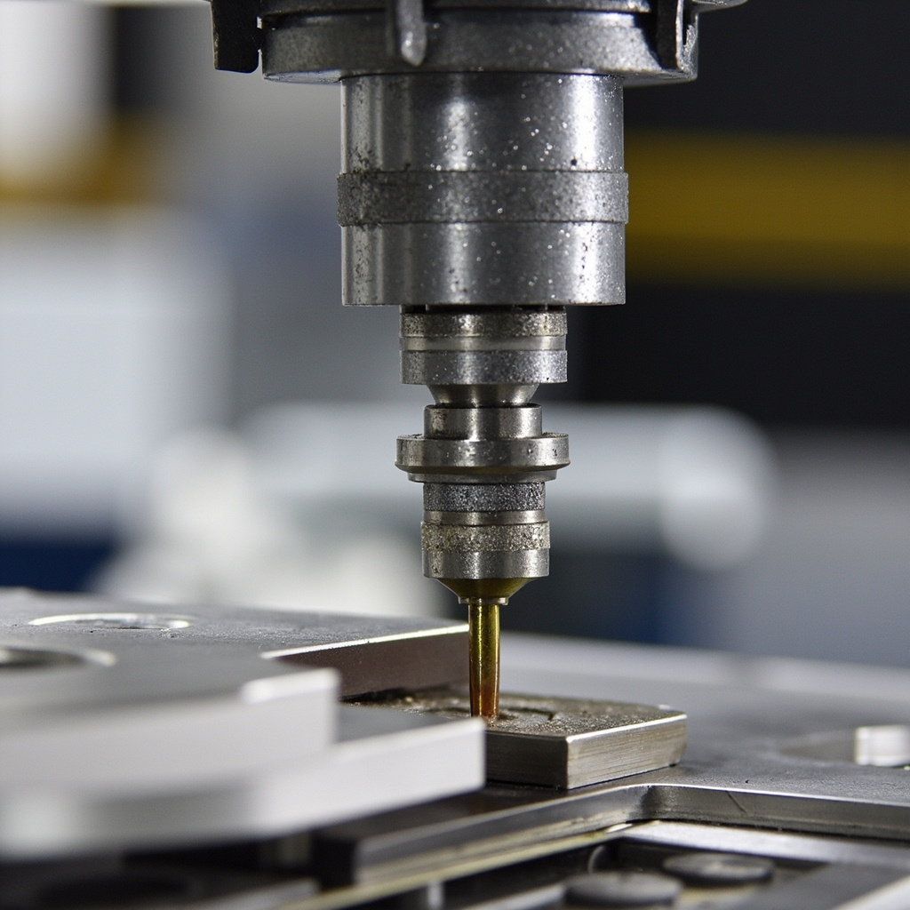
melt temperature. Weld lines are weak points and stress concentrators. Fix: raise melt temperature, redesign gate locations, add venting at weld line locations.
Burning Marks
Dark spots or streaks near the end of fill, typically from trapped air that ignites. Caused by excessive injection speed, poor venting, or excessive moisture in material. Fix: reduce injection speed, add vacuum vents, verify material dryness.
Injection Molding vs. Other Processes
| Factor | Injection Molding | CNC Machining | 3D Printing |
|---|---|---|---|
| Best for Quantity | 1,000+ parts | 1-500 parts | 1-100 parts |
| Tolerance | +/-0.05 mm typical | +/-0.01 mm achievable | +/-0.1-0.5 mm typical |
| Surface Finish | Mold finish dependent | Tool mark dependent | Layer lines visible |
| Tooling Cost | High ($10K-$500K+) | Low-medium | None |
| Material Waste | Sprue/runner system | Chip evacuation | Support structures |
Our Injection Molding Capabilities
We offer injection molding services for prototyping and low-to-mid-volume production:
- Multi-cavity tooling for competitive unit pricing at moderate volumes
- Overmolding and insert molding for multi-material assemblies
- Hot runner and cold runner systems optimized for part requirements
- Full DFM analysis before mold construction to minimize defects
Related Articles
Explore more manufacturing insights: CNC vs 3D Printing.
Frequently Asked Questions
What is the minimum order quantity for injection molding?
Technically, a mold can produce a single part. However, the per-part cost is prohibitive below roughly 500-1,000 pieces due to tooling amortization. For very low quantities (1-100 pcs), CNC machining or 3D printing are more cost-effective options. We can help you evaluate the crossover point based on your part geometry.
How long does it take to build an injection mold?
Standard steel molds for prototype quantities typically take 4-8 weeks. Complex multi-cavity production molds can take 10-16 weeks. Aluminum prototype molds offer faster turnaround (2-4 weeks) with lower tooling costs, suitable for 5,000-50,000 shot volumes.
Why must plastic be dried before injection molding?
Most engineering plastics are hygroscopic—they absorb moisture from the air. When molten plastic containing moisture is injected into a mold, the water flashes to steam, causing splay (silver streaks), reduced mechanical properties, and surface defects. Drying at the material’s recommended temperature (typically 80-100 degrees C for 2-4 hours) before molding is essential.
What is the difference between hot runner and cold runner?
Cold runner systems retain the sprue and runner system in the mold between shots—it solidifies and is ejected with each part as scrap. Hot runner systems keep the runners molten using electric heating elements, so no runner scrap is generated. Hot runners reduce material waste by 5-25% but increase mold cost and complexity.
 English
  Dutch
Dutch  German
  French
  Korean
  Russian
  Japanese
  Spanish
  Vietnamese
  Chinese
  Portuguese
  Arabic