A well-designed snap fit is engineering elegance—a single polymer feature that replaces screws, clips, adhesive, and assembly labor in one molding cycle. The challenge: snap fit design lives at the intersection of material science, mold flow analysis, and structural mechanics. Get the beam length, deflection angle, or material selection wrong by 10%, and your tool-less assembly becomes a field failure.
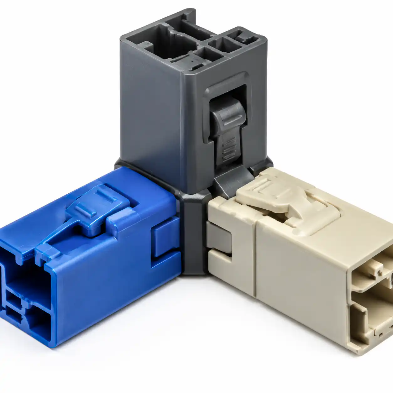
This guide covers the three fundamental snap fit types, material-dependent design equations, and the practical mold design considerations that separate prototypes from production-ready parts.
For engineering and sourcing teams
Reviewing a Snap Fit Before Mold Release?
A snap fit should be checked as a material, geometry, assembly and tooling system. Beam strain, root radius, draft, undercut direction and repeated-use requirements can all change the final design.
- Define one-time assembly or repeated service before sizing the feature
- Check allowable strain in the conditioned production material
- Confirm parting line, shutoff, ejection and side-action requirements
Request a snap fit DFM review → Review core and cavity design guidance
The Three Fundamental Snap Fit Types
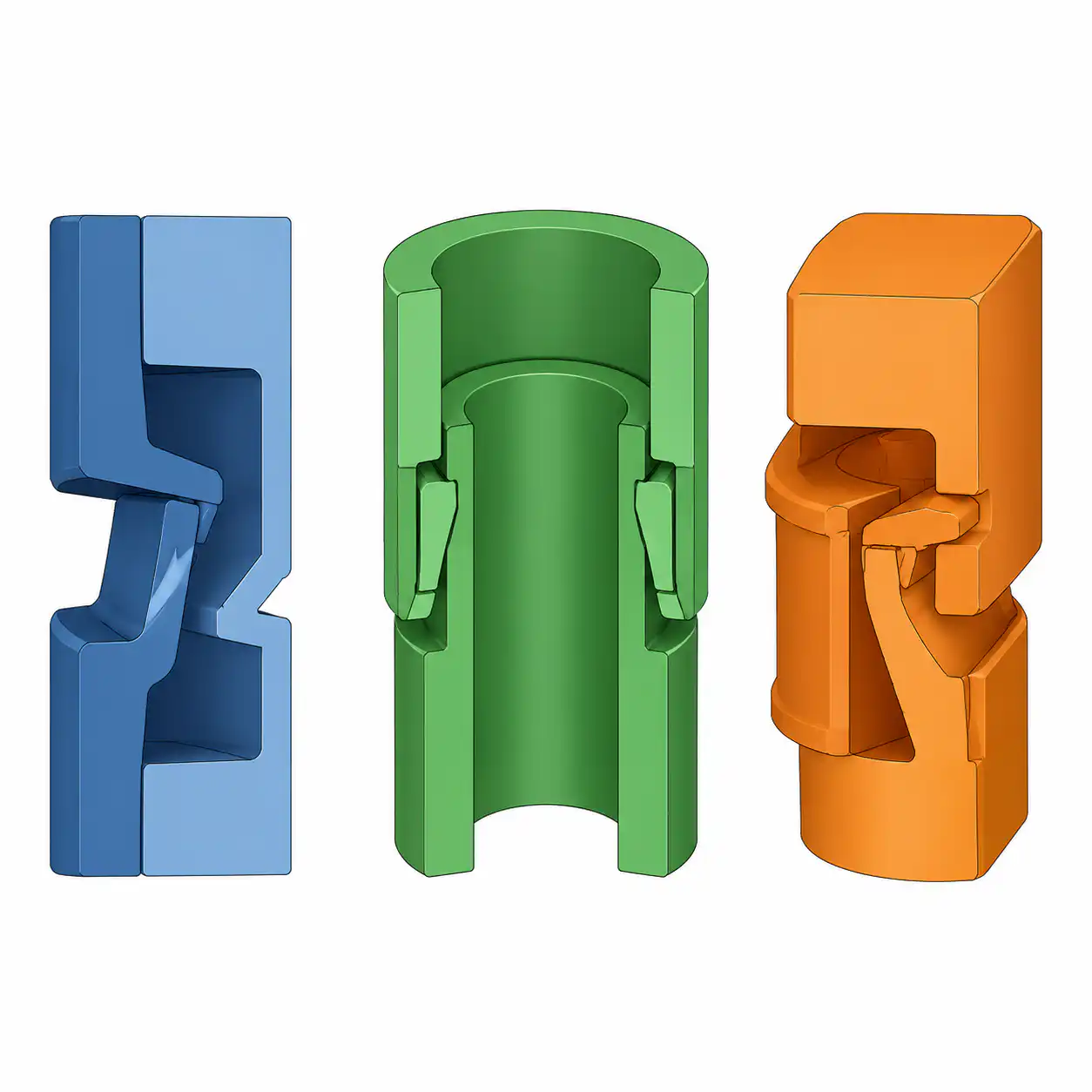
Every snap fit design derives from one of three basic geometries, each with its own stress distribution and application sweet spot:
| Type | Deflection Mode | Stress Concentration | Best For |
|---|---|---|---|
| Cantilever Beam | Bending | At root (max bending moment) | Enclosure covers, battery doors—80%+ of all snap fits |
| Annular (Cylindrical) | Hoop expansion | Distributed around circumference | Pen caps, tube connectors, ball-and-socket joints |
| Torsional | Torsion | At torsion bar ends | Hinges, latches, living hinges requiring repeated flex cycles |
Material-Dependent Design Limits
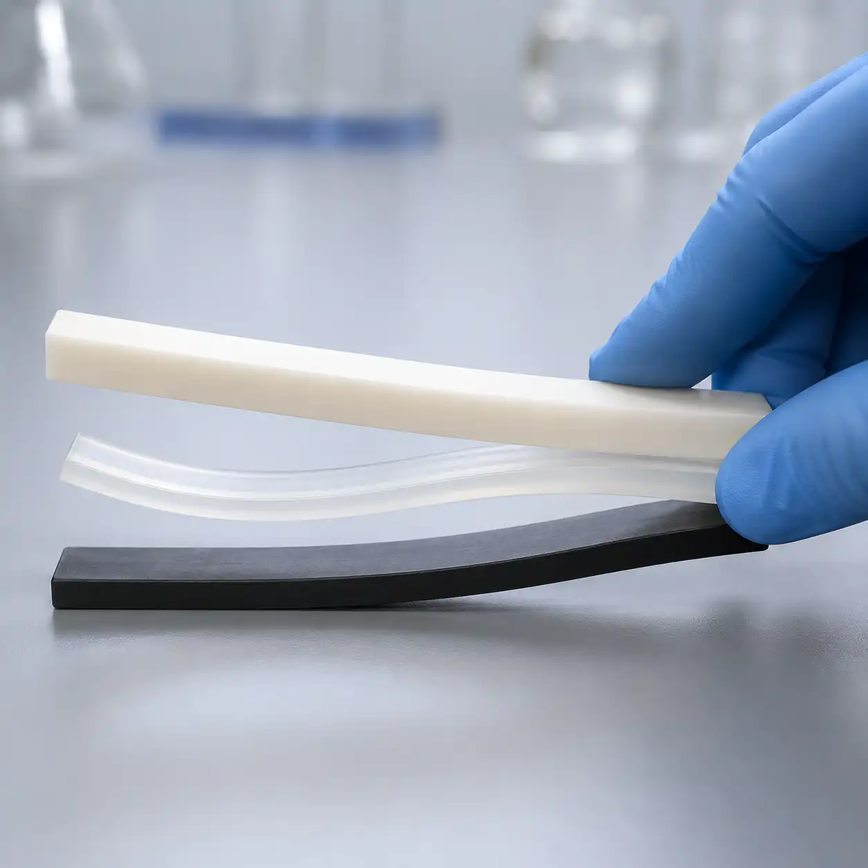
The governing equation for a cantilever snap fit derives from classical beam theory. For a rectangular cross-section beam: yₘₐₓ = (2/3) × (ε_yield × L²) / (h × Q), where Q is the deflection magnification factor (1.5-2.0 for tapered beams). The critical constraint is the material’s yield strain—and this varies dramatically between materials.
| Material | ε_yield | Max y/L Ratio | Snap Fit Grade |
|---|---|---|---|
| Polycarbonate (PC) | 4-5% | 0.10-0.12 | ⭐⭐⭐⭐ Excellent |
| Nylon 6 (PA6, conditioned) | 5-8% | 0.12-0.15 | ⭐⭐⭐⭐⭐ Best in class |
| ABS | 2.5-3.5% | 0.05-0.07 | ⭐⭐⭐ Good, common in consumer |
| PA66 GF30 | 1.5-2.0% | 0.03-0.04 | ⚠ Short beams only (<5× thickness) |
| POM (Acetal) | 3-4% | 0.06-0.08 | ⭐⭐⭐ Good, but susceptible to creep |
⚠ Critical warning: Glass-filled materials have yield strains 2-4× lower than unfilled grades. A snap fit dimensioned for unfilled PA6 will fracture immediately if molded in PA6 GF30. Always verify material-specific strain limits before committing to tooling.
For a nylon joint, compare PA6 and PA66 injection-molding requirements before choosing the exact grade.
Design Rules for Injection Molded Snap Fits
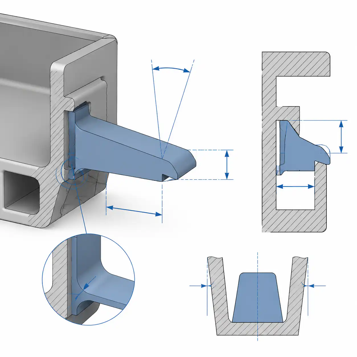
- Beam aspect ratio: Length-to-thickness ratio 5:1 to 10:1. Below 5:1, deflection too stiff; above 10:1, buckling risk and unreliable mold filling.
- Taper: Reduce beam thickness linearly from root to tip by 25-50%. Tapering distributes bending strain evenly, increasing allowable deflection by 40-60%.
- Root radius: Minimum 0.5 mm radius at beam root. Sharp corners create stress concentrations exceeding 3× nominal bending stress—guaranteed fracture initiation.
- Undercut depth: Keep retention undercut to 0.5-1.5 mm. Deeper undercuts need longer beams and increase mold complexity (lifter/slide required).
- Gate location: Never gate directly at the snap fit root. A root-gated snap loses 30-50% strength from the weld line. Gate on the opposite side of the part.
- Mold split line: Position snap fit entirely in one mold half. A parting line through a snap beam creates flash that acts as a crack initiator.
The chamfer and fillet guide provides a closer look at corner geometry for molded parts.
Industry Application Matrix
| Industry | Typical Parts | Snap Type | Preferred Material |
|---|---|---|---|
| Consumer Electronics | Phone cases, remote housings, laptop bezels | Cantilever (multiple) | PC/ABS—stiffness + toughness + finish |
| Automotive | Interior trim panels, HVAC vents, fuse covers | Cantilever + Annular | PP-TD20—low cost, good snap performance at interior temps |
| Medical | Disposable device housings, vial holders | Cantilever | PP homopolymer—sterilizable, >1M hinge cycles |
| Industrial | Machine guards, electrical enclosures | Cantilever (heavy) | PA6 conditioned—toughness + 80°C continuous service |
Cost Decision Framework
Snap fits incur zero incremental part cost and zero assembly labor cost—the most cost-effective fastening method in injection molding. A single cantilever snap replaces approximately $0.03-0.08 in screw + insert + assembly cost per joint.
For a product with 6 snap fits replacing 6 screws and brass inserts, per-unit savings is roughly $0.30-0.50. At 100,000 units/year, that’s $30,000-50,000 in annual savings.
Trade-off: Snap fits increase mold complexity. A mold with 4 undercut features requires lifters/slides adding $2,000-5,000 each. The ROI is compelling: mold cost recovered within 10,000-20,000 parts through assembly savings.
For a nylon enclosure or clip project, the nylon injection-molding service scope explains the part, tooling and quotation information to prepare.
Common Defects and Solutions
| Defect | Appearance | Root Cause | Solution |
|---|---|---|---|
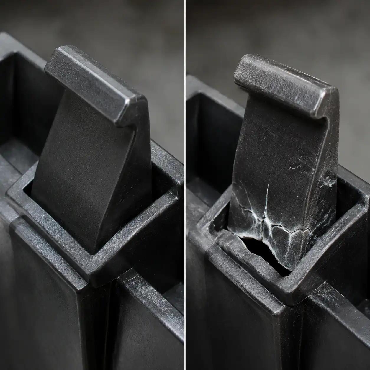
| Fracture on first engagement | Snap beam breaks before full engagement | Deflection exceeds material yield strain | Increase beam length 20-30%; taper profile; switch to higher-strain material |
| Creep relaxation | Snap loses retention force over weeks/months | Constant stress exceeds creep limit at service temp | Reduce engagement strain to <50% yield; use glass-filled; add secondary lock |
| Fatigue failure | Snap breaks after repeated use (50-500 cycles) | Strain amplitude too high for fatigue life target | Keep strain ≤20% yield for >10K cycles; generous root radius |
| Mold sticking | Snap beam tears or scuffs during ejection | Insufficient draft or undercut on sidewalls | Add 0.5-1° draft on all vertical surfaces; polish to SPI A2 or better |
At a Glance
| Decision Point | What Matters Most | Buyer Note |
|---|---|---|
| Deflection | Material strain limit | Keep the snap below its safe flex range |
| Root stress | Radius and thickness | Control the root first to avoid early failure |
| Assembly force | Lead-in angle and draft | Reduce insertion effort without weakening retention |
| Best use | Repeatable enclosure and housing assembly | Design for assembly, not just retention |
Frequently Asked Questions
Can Nylon Plastic recommend a material for a snap fit?
The review can compare unfilled PA, PA-GF20, PA-CF30 and other engineering plastics against allowable strain, fatigue, moisture, temperature and assembly use. The final recommendation needs the actual beam geometry and cycle requirement.
Can a snap-fit undercut be molded without a side action?
Sometimes a flexible part can strip from the tool, but the decision depends on undercut depth, material strain, draft, surface and ejection direction. Tooling review is required before assuming a simple mold.
How should a repeated-use snap fit be validated?
Define the assembly cycle count, insertion and retention force limits, temperature and conditioning state. Test representative production-material parts after aging or environmental exposure when those conditions matter.
What should be sent for a snap-fit DFM quote?
Send both mating CAD models, drawings, assembly direction, force targets, material preference, cycle requirement, annual volume and any cosmetic or tooling restrictions.
What is the most common snap-fit design mistake?
The most common mistake is checking only initial retention while ignoring root strain, moisture-conditioned dimensions, assembly speed and repeated cycles. Review the root radius and material condition before finalizing the mold.
Related Reading
Request a Custom Snap-Fit Review
For an injection-molded snap-fit enclosure, cover or clip, review both mating parts before mold release. Nylon Plastic can connect material selection, joint geometry, mold design and sample manufacture so the quotation addresses assembly and tooling together.
What to include and agree before quotation
Project details:
- CAD for both mating components and the assembly direction
- One-time or repeated-use requirement and target cycle count
- Insertion, retention and allowable removal force
- Material, conditioning state and operating environment
- Annual volume, appearance class and validation method
DFM support, NDA arrangements, material or composition documentation and inspection requirements can be discussed during quotation. Availability depends on the project scope and agreed quality plan.
Manufacturing and delivery:
- Precision Manufacturing: 30+ CNC & injection molding cells under one roof
- ISO 9001:2015: Certified quality system, full inspection reports
- 15-25 Day Lead Time: Fast turnaround with expedited options available
- Global Shipping: Air & sea freight to North America, Europe, Asia
📥 Download Snap Fit Design Guide (PDF)
Nylon Plastic combines material modification with product design, mold design and making, injection molding, CNC machining and 3D printing. The right scope is selected from the drawing and service conditions rather than promised from a generic material name.
| Customization Area | Options to Review | Information Needed |
|---|---|---|
| Material choice | Unfilled or reinforced nylon and alternative polymer review | Assembly cycles, strain, temperature, moisture and chemical exposure |
| Joint geometry | Cantilever, annular or torsional concept and tolerance review | CAD, mating part, insertion force and retention target |
| Tooling strategy | Parting line, shutoff, draft, ejection and side-action DFM | Undercut direction, cosmetic zones and mold constraints |
| Validation route | 3D print, CNC, prototype tool or production mold planning | What must be tested and how closely it must represent production material |
Agree which trials check geometry only and which must use the conditioned production grade. The quotation should distinguish component manufacture, mold actions or changes, trial assemblies, cycle/force checks and inspection records.