
Polycarbonate (PC) offers exceptional strength, heat resistance, and optical clarity—making it ideal for demanding applications. However, it’s also one of the most challenging materials to print. This guide covers everything you need to succeed with PC.
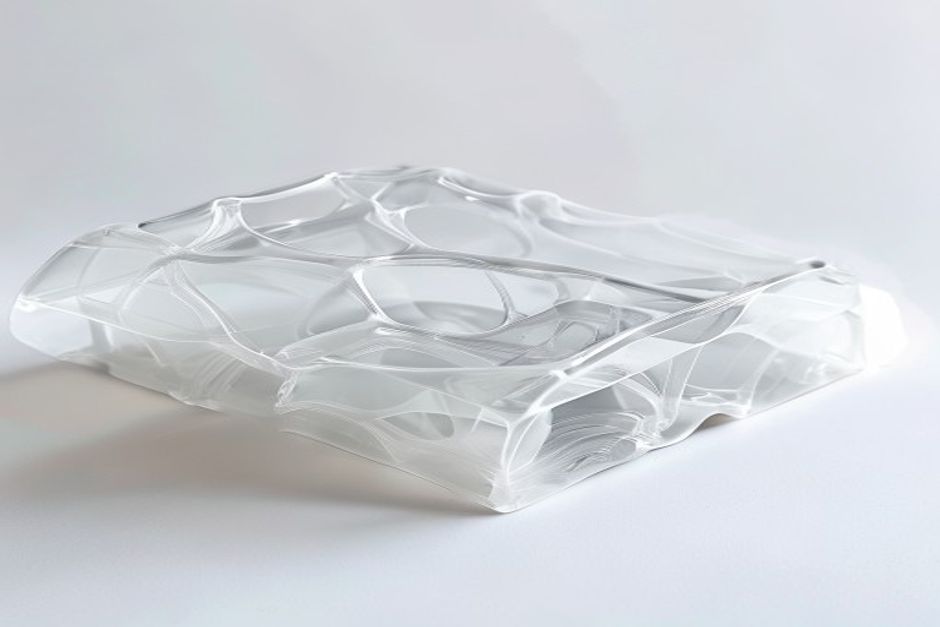
Why Print with Polycarbonate?
PC stands out for its exceptional properties:
- Heat resistance: Glass transition at 147°C
- Impact strength: Nearly unbreakable at room temperature
- Optical clarity: Transparent prints possible
- Dimensional stability: Low thermal expansion
PC-ABS blends offer easier printing while maintaining many benefits.
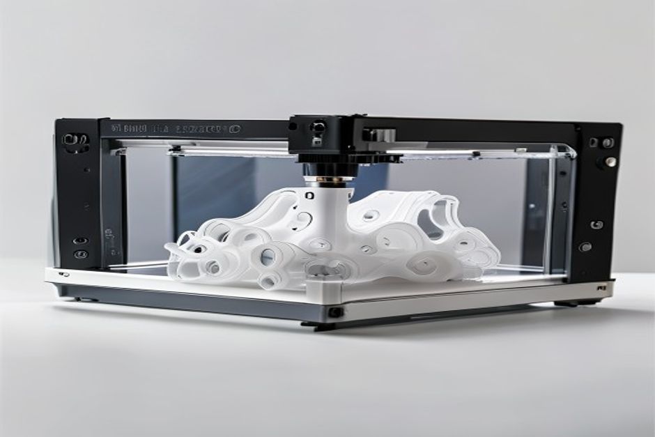
Essential Equipment
Hotend Requirements
PC requires high temperatures:
| Component | Minimum Spec | Recommended |
|---|---|---|
| Max temp | 290°C | 300°C+ |
| Nozzle | Brass works | Hardened steel |
| Heat break | All-metal | Required |
Warning: PTFE-lined hotends cannot handle PC temperatures safely.
Enclosure
Non-negotiable for successful PC printing:
- Minimum: 50°C ambient temperature
- Optimal: 70-80°C chamber
- Purpose: Prevent warping, improve layer adhesion
Like ABS, PC requires thermal stability.
Build Surface
Proven options:
1. PEI at 110-120°C — Most reliable
2. Garolite — Excellent for larger parts
3. PC sheet — Bond extremely well
Optimal Print Settings
Temperature
| Parameter | Range | Notes |
|---|---|---|
| Nozzle | 270-310°C | Start at 290°C |
| Bed | 110-130°C | PEI needs 115°C+ |
| Chamber | 50-80°C | Higher is better |
Speed and Layer Height
- Speed: 20-40mm/s recommended
- Layer height: 0.2mm minimum
- First layer: 50% speed
Cooling
- Minimum fan: 0-20%
- Never: Use maximum cooling
- Exception: Very small features
Troubleshooting Common Issues
Warping
Causes:
- Insufficient bed temperature
- Enclosure too cold
- Drafts from cooling
Solutions:
- Increase bed to 120°C
- Improve enclosure sealing
- Add draft shield in slicer
Poor Layer Adhesion
Causes:
- Nozzle too cold
- Cooling fan too high
- Layer time too long
Solutions:
- Increase nozzle 5-10°C
- Reduce or eliminate cooling
- Print multiple parts simultaneously
Bubbles/Pitting
Causes:
- Moisture in filament
- Temperature too high
- Filament degradation
Solutions:
- Dry filament at 80°C for 4 hours
- Reduce nozzle temperature
- Check for nozzle degradation
Special Techniques
Annealing PC Prints
Post-print heat treatment improves properties:
1. Place print in oven at 120°C
2. Hold for 30-60 minutes
3. Cool slowly in oven
4. Expect slight dimensional change
Bonding PC Parts
- Solvent welding: Methylene chloride (effective but toxic)
- Epoxy: Works well for most applications
- Friction welding: Creates strong bonds
 English
 Dutch
Dutch German
 French
 Korean
 Russian
 Japanese
 Spanish
 Vietnamese
 Chinese
 Portuguese
 Arabic