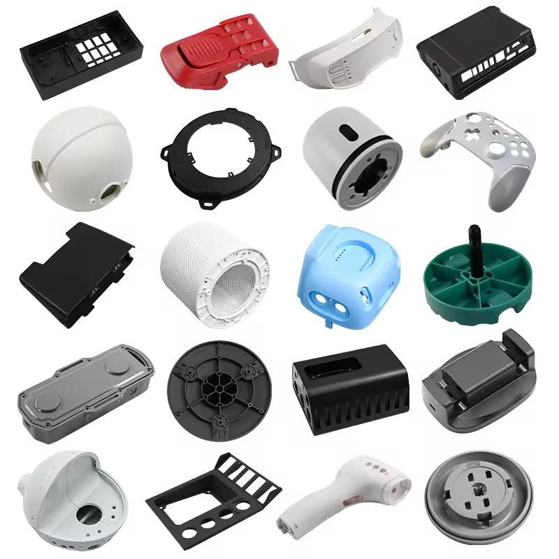
Electrical connector injection molding requires tight control of resin, terminal position, flash, warpage, insulation performance and mating interfaces. Connector housings are often small, but their functional chain includes cavities, latches, seals, contacts, PCB interfaces and mating parts that leave little room for uncontrolled variation.
A capable supplier reviews the connector as an assembly, not just as a plastic shell. The housing CAD, terminal drawing, resin grade, sealing plan, inspection method and validation requirements should be aligned before the mold is released.
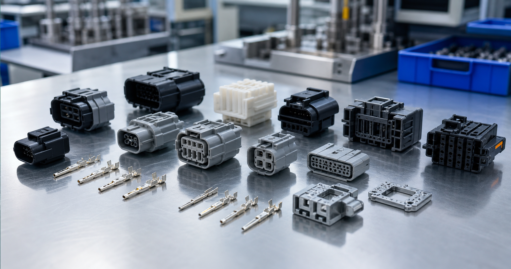
Connector Requirements and Failure Consequences
Start with terminal pitch, contact position, latch geometry, seal compression, creepage and clearance, housing datum, mating force and service environment. A small shift can increase insertion force, interrupt electrical contact, damage a seal, reduce terminal retention or prevent assembly. The supplier needs the complete mating interface, not only the housing model.
| Critical area | Why it matters | Evidence to request |
|---|---|---|
| Terminal position | Controls contact alignment, pitch and mating force | Insert fixture, datum plan and position report by cavity |
| Flash-sensitive zones | Flash can block contacts, seals or latch movement | Defined limits, visual standard and shutoff maintenance record |
| Housing warpage | Changes pitch, coplanarity and mating-face alignment | Free-state fixture, dimensional map and process evidence |
| Electrical performance | Material and geometry affect insulation, heat and reliability | Grade data, CTI/UL evidence and application-specific testing |
| Traceability | Failures must be linked to resin, terminal, tool and cavity | Lot, cavity, machine, process and inspection records |
Material Selection for Connector Housings
PA66, PBT, PPS, LCP, PPA and other reinforced or flame-retardant grades can be suitable, but selection depends on temperature, moisture, dielectric performance, CTI, UL requirements, mechanical load, mating cycles and assembly process. A material should not be approved only because it worked in another connector design.
| Resin family | Typical direction | Processing or design risk |
|---|---|---|
| PBT | Dimensional stability and common electrical connector use | Hydrolysis control, glass-flow warpage and grade-specific flame/CTI data |
| PA66 | Toughness, strength and broad reinforced-grade availability | Moisture-driven dimensions and mandatory drying control |
| LCP | Thin walls, fine pitch, fast cycles and high-temperature grades | Strong flow orientation, weld-line behavior and brittle features |
| PPS | Heat and chemical resistance with dimensional stability | Brittleness, flash control and tooling wear with reinforcement |
| PPA | High-temperature capability and strength | Moisture management, warpage and exact grade qualification |
Confirm the exact grade using operating and processing temperature, CTI, dielectric requirements, UL listing, moisture exposure, mating cycles and dimensional capability. Polymer-family comparisons cannot replace the approved datasheet and product validation.
Terminal Preparation and Positioning
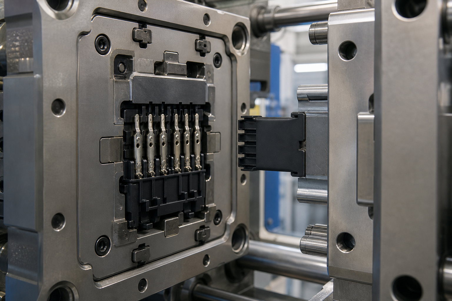
Terminals must be clean, dimensionally stable and consistently presented to the mold. The nest should support each insert against injection pressure without scratching contact surfaces. Use poka-yoke features, presence sensors or vision checks when a missing or reversed terminal creates a serious risk. Define terminal position before and after molding so the team can separate incoming insert variation from molding movement.
Reel or tray presentation, plating, cut-off condition, carrier design and allowable deformation belong in the RFQ. The tool should provide positive location and practical loading access, while protecting contacts from resin flash and unnecessary handling damage.
Thin Walls, Shutoffs, Flash and Warpage DFM
Fine-pitch housings require balanced filling through thin sections without freezing off. Steel shutoffs around terminals need realistic angles, suitable hardness and maintenance access. Flash limits should be zoned: a small amount near a seal, contact cavity or latch may be critical even when the same amount is acceptable elsewhere.
Reinforced resin orientation, unequal walls and unbalanced cooling can shift pitch or bow the mating face. Review gate location, venting, cooling and ejection against the functional datum scheme. Draft, weld-line position, ejector marks and the parting line should be agreed before steel release.
Gate, Venting, Cooling and Cavity Balance
Gate location influences weld lines, terminal movement, fiber orientation, vestige risk and fill balance. Vents must release trapped gas near thin-wall endpoints while resisting flash. Cooling should stabilize the connector face and latch features uniformly. In a multi-cavity tool, report dimensions and defects by cavity; pooled data can conceal one weak cavity.
| Tooling control | Failure it helps prevent | Buyer acceptance evidence |
|---|---|---|
| Terminal nests and sensors | Missing, reversed or shifted inserts | Loading standard, presence check and terminal-position report |
| Shutoffs and parting surfaces | Flash in cavities, seals or latch zones | Flash map, wear limit and maintenance access |
| Balanced gate and cooling layout | Pitch drift, warpage and cavity imbalance | Short-shot/trial evidence and cavity-separated dimensions |
| Venting near end of fill | Burns, short shots and weak weld lines | Vent inspection, defect map and approved process window |
Insert Molding, Housing-Only Molding and Assembly
Insert molding can reduce assembly steps and improve terminal retention, but it demands stable insert supply, precise loading, mold protection and reliable inspection. Housing-only molding may be better when contacts are installed later or when multiple terminal variants share one body.
Choose the route around total assembly capability, quality risk and volume. A lower molded-part price does not create savings if terminal loading, contact inspection or downstream assembly becomes unstable. Include the mating connector, seal, cable or PCB interface in the decision.
Electrical, Dimensional and Visual Inspection
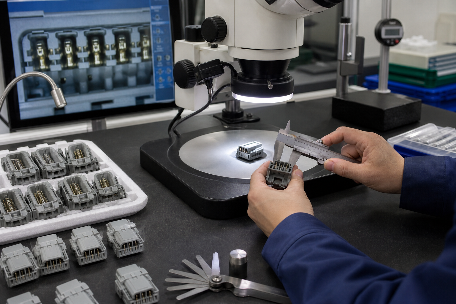
Inspection commonly covers terminal position, pitch, coplanarity, housing profile, seal lands, latch geometry, flash, short shots and contamination. Functional evidence may include continuity, insulation resistance, dielectric withstand, mating force, terminal retention and leak testing when specified.
Use fixtures based on actual mating datums and conduct MSA on critical measurements. Flexible latches and thin housings need controlled fixturing force. Identify drawing revision, tool and cavity, resin and terminal lots, process status, sample quantity, instrument and disposition in the report.
FAI, PPAP and Lot Traceability
The approval package should identify the drawing revision, tool and cavity, resin and terminal lots, process settings, dimensional results, material evidence and deviations. Automotive or customer-controlled programs may require PPAP elements and capability data. Traceability should connect finished lots to resin drying records, molding machine, cavity, terminal batch and inspection results.
Before routine production, confirm that the inspection method can distinguish terminal variation from molding variation. Repeat relevant approval work after a material, terminal, tool, cavity, process or supplier change when the change can affect fit, sealing or electrical performance.
Common Connector Molding Risks
| Risk | Typical cause | Practical control |
|---|---|---|
| Terminal moves during molding | Insert support, loading repeatability or injection balance is inadequate | Improve nest design, sensing and the validated process window |
| Flash blocks a seal or cavity | Shutoff wear, alignment or clamp condition is poor | Define critical zones, inspect wear and retain flash limit samples |
| Housing warps after ejection | Gate, cooling or reinforced flow orientation is unbalanced | Review flow/cooling, condition samples and map the mating face |
| Cracking during mating | Resin, weld line, latch geometry or assembly force is unsuitable | Review material, gate, strain, cycle testing and mating force |
| Electrical test failure | Wrong grade, contamination, moisture or inadequate spacing | Control material records, cleaning, drying, CTI and product testing |
Qualification Tests for Connector Programs
Agree on the qualification sequence before the first tool trial. Dimensional results explain where variation occurs, while functional tests show whether that variation matters to the complete connection. Use the same terminal, mating connector, seal, cable, PCB interface and test fixtures that will be used for approval whenever possible.
| Test or evidence | What it demonstrates | Variables to control |
|---|---|---|
| Mating and unmating force | Housing, latch and contact alignment support assembly | Connector pair, insertion speed, lubrication, cycle count and temperature |
| Terminal retention | Contacts remain secured under specified load | Terminal lot, pull direction, sample location and acceptance force |
| Continuity and insulation | Electrical paths and isolation meet the application requirement | Voltage, current, dwell, humidity, contamination and fixture connection |
| Seal or leak test | Housing, gasket, wire exit and mating interface control leakage | Pressure, time, temperature, compression, cable and test medium |
| Thermal or environmental cycling | Material, latch, seal and terminal performance remain stable in service | Temperature range, dwell, ramp, humidity, cycles and post-test inspection |
Change Control and Production Continuity
Connector programs can change through resin substitutions, terminal plating updates, tool maintenance, cavity repairs, molding-cell transfers or new mating components. Require the supplier to identify affected characteristics before the change is released. A material, terminal or tool change may alter flash, pitch, retention, insulation, sealing or mating force even when the part number stays the same.
Keep the approved drawing, resin and terminal records, cavity map, process window, inspection method, limit samples and qualification results together. Repeat the relevant dimensional, electrical, mating or environmental tests when the change can affect the approved interface.
Electrical Connector Molding RFQ Checklist
- Housing, terminal and mating-part CAD plus controlled drawings and pin map.
- Exact resin grade, color, CTI/UL requirements and environmental range.
- Terminal material, plating, presentation method and allowable deformation.
- Critical flash zones, terminal position, pitch, coplanarity and datum scheme.
- Annual demand, cavity target, program life and automation scope.
- Mating force, retention, sealing, electrical and environmental test requirements.
- FAI/PPAP level, capability expectations, traceability and report format.
Share the complete connector assembly rather than only the housing CAD. We can review material, terminal loading, tooling, inspection and validation risk before quoting the production route.
Connector Molding Acceptance Questions
- Which dimensions control mating, terminal retention, seals, PCB alignment, and latch function?
- Are the resin, color, flame rating, CTI or insulation requirement, moisture state, and approved alternatives defined?
- Will terminal insertion, pull-out, crimp position, dielectric tests, fit checks, and visual limits be sampled by cavity and lot?
- What change-control evidence is required for resin, mold steel, cavity balance, process settings, packaging, or sub-supplier changes?
How Nylon Plastic Supports the Project
Nylon Plastic has supported material selection and finished plastic-part manufacturing since 2005. For electrical connector injection molding, the useful review connects the drawing, material, tooling or machining route, inspection state, and production plan before a quote is approved.
- Review PA66, PA-GF20, PBT, LCP, and other candidate resins against heat, flame, insulation, moisture, terminal interface, and volume requirements.
- Coordinate mold design, insert or terminal positioning, cavity identification, dimensional reports, and functional validation before release.
- Keep material lot, process revision, cavity, inspection, PPAP or equivalent records connected through production and reorders.
Related Reading
Frequently Asked Questions
Which materials are common for electrical connector molding?
PA66, reinforced nylon, PBT, and LCP are common directions, but the correct grade depends on temperature, flame, insulation, CTI, moisture, terminal interface, geometry, and approval requirements.
How are terminals controlled during insert molding?
The mold and fixture must control terminal position, support, retention, shorting risk, flash, and repeatability. Validate the actual terminal, housing, and assembly rather than the plastic housing alone.
What connector dimensions are usually critical?
Mating envelope, terminal position, latch, seal, PCB interface, cavity alignment, flash zones, and wall or shutoff features are common critical areas. Mark them on the controlled drawing.
What should a connector molding RFQ include?
Include housing and terminal CAD, resin specification, annual volume, cavity target, mating parts, critical dimensions, electrical tests, appearance limits, traceability, and validation requirements.
Request an Electrical Connector Molding Review
Send the housing and terminal files, resin requirement, annual volume, mating interfaces, and validation plan for a supplier and process review.