
Sheet Metal Fabrication: Bending, Cutting, and Assembly — Practical Manufacturing Guide
Here’s a question I get at least twice a week: “Should I make this out of sheet metal or CNC machine it from solid?” The answer usually surprises people. Sheet metal isn’t just “cheaper CNC” — it’s a completely different manufacturing logic. You don’t design a sheet metal part the way you design a machined part. You think in bends, not cuts. You think in flat patterns, not solid blocks.
I’ve seen brilliant mechanical engineers design beautiful machined housings, then get quoted $400 each, only to realize a sheet metal version would do the same job for $40. And I’ve also seen the reverse — engineers trying to force a complex geometry into sheet metal when machining was clearly the right call.
This guide is for the engineer who needs to make that call. Let’s walk through what sheet metal fabrication actually looks like on the shop floor, what processes you’re really choosing between, and how to design parts that come out right the first time.
Core Concepts & Fundamentals — How Sheet Metal Actually Works
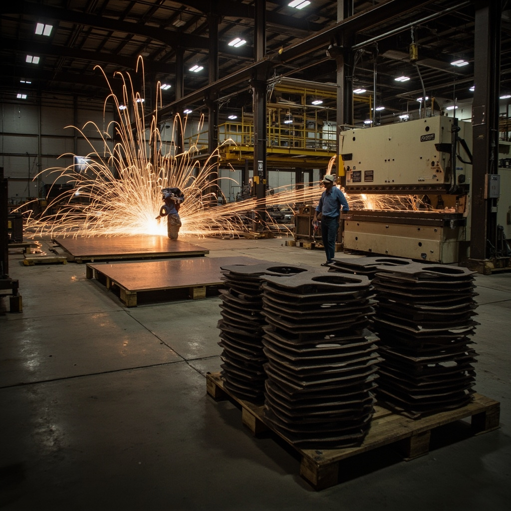
Sheet metal fabrication starts with flat material — coils or sheets of steel, aluminum, stainless, copper, or brass — and shapes it through cutting, bending, punching, and joining. No material is removed (mostly). The geometry comes from deformation, not subtraction.
This is fundamentally different from CNC machining. In machining, you start with a billet and remove everything that isn’t your part. In sheet metal, you start with a blank and bend it into shape. The manufacturing logic, the design rules, and the cost drivers are completely different.
The five core sheet metal processes every engineer should know:
1. Cutting. Getting your flat blank out of the sheet. Laser cutting dominates today — fast, precise, no tooling cost. Plasma cutting handles thicker material (6mm+) at lower precision. Waterjet handles materials that don’t like heat. And the old-school turret punch is still great for high-volume runs with standard hole patterns.
2. Bending. The defining sheet metal process. A press brake with a punch and die set bends the flat blank along a straight line. The quality of your bend depends on three things: the tooling radius, the material properties, and the bend allowance calculation in your flat pattern.
3. Punching. Creating holes, louvers, embossments, and other features by punching through the material with a tool and die set. Faster than drilling for production, but each feature needs dedicated tooling or a CNC turret punch with standard tool libraries.
4. Welding. Joining bent parts into assemblies. TIG for aluminum and stainless, MIG for steel production work, spot welding for sheet-to-sheet lap joints. Welding introduces heat distortion — you need to account for it in your tolerances or fixture your parts aggressively.
5. Finishing. Powder coating, wet painting, plating, anodizing (aluminum only), or passivation (stainless). Sheet metal parts almost always get some kind of finish for corrosion protection. The finish choice affects your bend sequence — you usually finish after bending, but some coatings crack if applied after forming.
Gauge vs. millimeter. Sheet metal thickness is still commonly specified in gauge numbers in the US, which is confusing because gauge goes down as thickness goes up. 16 gauge steel is about 1.5mm. 10 gauge is about 3.4mm. Save yourself and your international suppliers the headache — specify thickness in millimeters on your drawings.
Key Processes & Technologies — The Shop Floor Toolbox
| Process | Best Material Thickness | Tolerance Capability | Tooling Cost | Best Application |
|---|---|---|---|---|
| Fiber Laser Cutting | 0.5–25mm (steel) 0.5–20mm (aluminum) | ±0.1–0.2mm | None — programmed from DXF | Prototypes to mid-volume, complex profiles, tight tolerances |
| CO₂ Laser Cutting | 0.5–20mm (steel) Limited on reflective metals | ±0.15–0.3mm | None | Steel and stainless, thicker sections, lower capital cost equipment |
| Plasma Cutting | 3–50mm+ | ±0.5–1.5mm | None | Thick plate, structural steel, rough tolerance applications |
| Waterjet Cutting | 0.5–100mm+ | ±0.1–0.3mm | None | Heat-sensitive materials, thick stacks, mixed-material cutting |
| CNC Press Brake Bending | 0.5–12mm typical | ±0.2–0.5° (angle) ±0.1–0.3mm (position) | Standard tooling $200–800/set Custom $1,000+ | Precision enclosures, brackets, chassis — 90% of sheet metal work |
| Turret Punching | 0.5–6mm | ±0.1–0.2mm | Standard tool library included Custom form tools $500+ | High-volume panels with standard holes, louvers, embossments |
| TIG Welding | 0.8–6mm | Depends on fixturing | Jigs $200–2,000+ | Aluminum and stainless — precision, cosmetic, food-grade welds |
| MIG Welding | 1.5–12mm+ | Depends on fixturing | Jigs $200–2,000+ | Steel production welding — faster than TIG, good for thicker material |
| Spot/Resistance Welding | 0.5–3mm per sheet | ±0.5–1mm (position) | Electrode tips $50–200 | Sheet-to-sheet lap joints, battery tabs, automotive body panels |
| Hardware Insertion | 0.8–6mm | ±0.1mm (position) | Insert tooling $100–500 | PEM nuts, standoffs, studs — creating threaded features in thin sheet |
A few things the chart above doesn’t capture. Fiber laser has mostly replaced CO₂ in modern shops — it cuts faster, handles reflective metals (aluminum, copper, brass) without a second thought, and the running costs are lower. If your shop still uses CO₂ for everything, they’re either cutting very thick steel or they haven’t upgraded yet.
Press brake tooling matters more than the brake itself. A worn-out punch radius produces inconsistent bend angles and more springback variation. Standard tooling (85° die, 0.8mm punch radius) covers 80% of jobs. The other 20% — tight radii, deep channels, hemming — needs specialized tooling that not every shop stocks.
On welding: TIG looks prettier but runs slower. MIG is faster but spatters and needs cleanup. For cosmetic sheet metal assemblies where the welds are visible, TIG wins. For internal brackets and structural frames that get powder coated anyway, MIG is the practical choice.
Industrial Applications — Where Sheet Metal Earns Its Keep
| Industry | Application | Material | Key Requirement | nylonplastic.com Advantage |
|---|---|---|---|---|
| Electronics | Server rack chassis | 1.5mm Cold Rolled Steel | ±0.2mm across 19″ mounting rails, powder coated black, EMI gasket surfaces | Laser-cut precision + CNC bending with PEM insertion — complete chassis from flat to finished |
| Medical | Diagnostic device enclosure | 1.2mm 304 Stainless Steel | Electropolished welds, no crevices, IP65 sealed seams, cleanroom-compatible | TIG-welded stainless fabrication with in-house electropolishing for full medical-grade finish chain |
| Automotive | EV battery mounting bracket | 3.0mm 5052 Aluminum | Structural rigidity, corrosion resistance, weight optimization, crash-load capable | Heavy-gauge aluminum bending + MIG welding capability with structural verification |
| Industrial Equipment | Machine guard / safety enclosure | 2.0mm Cold Rolled Steel | Quick-release panels, polycarbonate window integration, OSHA-compliant interlocks | Complete fabrication + hardware integration — enclosure ships ready to mount, not as a flat-pack |
| Robotic Automation | Robot cell frame and guarding | 3.0–5.0mm Steel Tube + Sheet | Welded structural frame, modular panel attachment, vibration-resistant | Tube laser cutting + sheet fabrication combined — frame and panels from one supplier |
| Furniture | Modular desk frame system | 2.0mm Cold Rolled Steel | Powder coat cosmetic finish, precision hole patterns for assembly, flat-pack ready | Laser-cut + bent + powder coated under one roof — consistent color batch-to-batch |
| Aerospace | Avionics mounting tray | 1.6mm 2024-T3 Aluminum | Weight-critical, vibration-tested, ±0.1mm mounting hole positions, alodine finish | Aerospace-grade aluminum fabrication with chemical conversion coating per MIL-DTL-5541 |
What jumps out from this table: sheet metal shows up everywhere there’s an enclosure, a bracket, a frame, or a panel. It’s the default manufacturing method for anything that wraps around other components. When you need a box that holds electronics, protects operators, or mounts a mechanism — sheet metal is almost always the answer.
The cross-over point with CNC machining typically sits around part complexity. If your part has 3D contours, deep pockets, internal threads, or tight bores — machine it. If your part is mostly flat with some bends, holes, and hardware — fabricate it. Hybrid designs are common too: machine the precision mounting plate, bolt it into a sheet metal enclosure.
Material Selection — What Actually Works on the Shop Floor
Sheet metal material choice isn’t just about strength and corrosion resistance. It’s also about bendability. Some materials form beautifully. Others crack if you look at them wrong.
Cold Rolled Steel (CRS / 1008-1010). The workhorse. Bends great, welds easily, takes powder coat beautifully. Available everywhere in every gauge. If you’re prototyping and don’t have a specific material requirement, start here. SPCC is the equivalent Japanese grade, DC01 is the European designation — same stuff, different name.
Hot Rolled Steel (HRS / A36). Cheaper than CRS but has mill scale on the surface — that dark gray oxide layer. You need to remove it (sandblasting or pickling) before powder coating or painting. Rougher surface finish, looser thickness tolerance. Use it for structural brackets, frames, and anything that’ll be hidden or heavily coated.
Stainless Steel (304). The most common stainless for sheet metal. Bends well but work-hardens — bent corners are harder than the flat areas. TIG welds beautifully. More springback than CRS — your bend angle needs more overbend to hit the target. 316L adds molybdenum for better corrosion resistance, typically used in marine and medical applications.
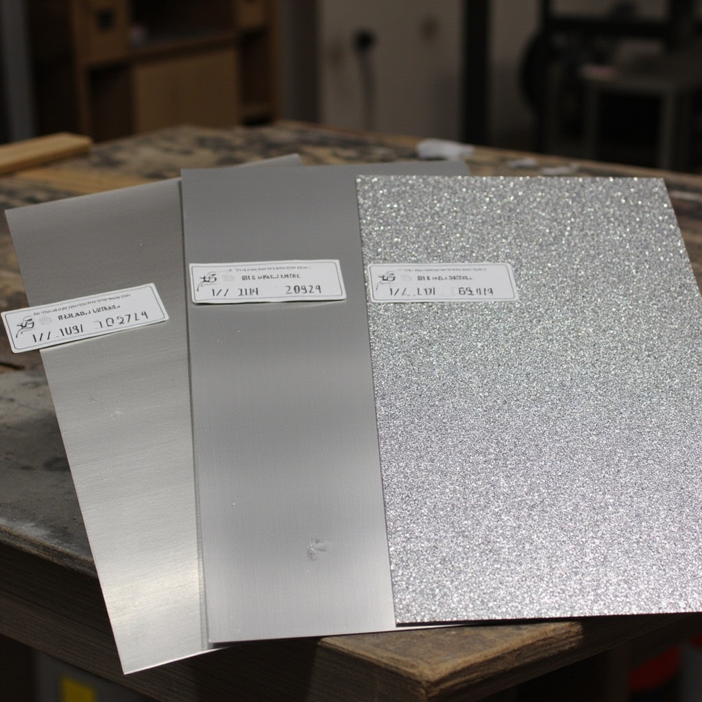
Aluminum (5052-H32). Your go-to for bent aluminum sheet metal. 5052 bends well with a reasonable bend radius (1-2x material thickness). 6061-T6 sheet is much harder to bend — it cracks at tight radii. If someone specs 6061-T6 sheet metal with tight bends, they’re going to get cracked corners in production. Unfortunately, I see this mistake regularly.
Galvanized Steel. Pre-coated with zinc for corrosion resistance. Bends fine, but the zinc coating can flake at tight bend radii. Welding galvanized steel produces zinc fumes — you need proper ventilation and the weld zone loses its corrosion protection. Post-weld touch-up with cold galvanizing spray is standard practice.
Copper and Brass. Beautiful materials that bend like butter. Extremely soft — watch out for tooling marks. Copper work-hardens quickly, so repeated bending or forming operations need intermediate annealing. Mostly used for decorative and architectural applications rather than structural.
The bendability check: minimum inside bend radius should be at least equal to material thickness for most steels and aluminum. For harder tempers (6061-T6, high-carbon steels), go to 2-3x material thickness. For 5052 aluminum and mild steel, you can often get away with a radius equal to 0.5x material thickness with the right tooling and grain direction.
Grain direction matters. Sheet metal has a grain from the rolling process. Bending perpendicular to the grain (the preferred direction) gives you a clean bend. Bending parallel to the grain can cause cracking, especially in harder materials. Your flat pattern layout should account for this — and a good shop will flag it if you don’t.
Cost & Performance Trade-offs
Sheet metal cost drivers are different from machining. There’s almost no material waste (you’re cutting from a sheet, not removing from a billet), but setup time and welding labor dominate the cost equation.
What drives sheet metal cost?
Material utilization. Laser cutting nests your parts on a standard sheet (typically 1220×2440mm or 1524×3048mm). Odd-shaped parts leave more skeleton — wasted material between parts. Rectangular parts nest tight. Good design for sheet metal minimizes the bounding box of your flat pattern. A clever flat pattern that nests efficiently can save 15-20% on material cost.
Number of bends. Each bend is a separate press brake setup or tooling change. A simple L-bracket with two bends runs fast. A complex chassis with 12 bends in different directions takes significantly longer. Every bend you can eliminate saves money. Every bend that shares the same tooling setup saves time.
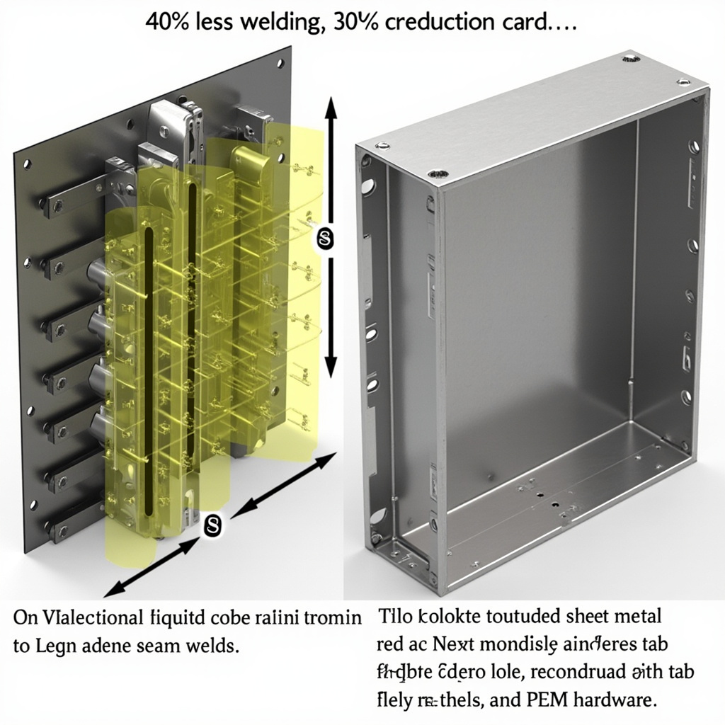
Welding vs. bending vs. hardware. A self-jigging design that slots and tabs together with minimal welding is always cheaper than a design that needs full seam welding. Consider PEM hardware (self-clinching nuts, studs, standoffs) instead of welded-on threaded bosses — faster to install, more precise position, and no heat distortion.
Finish sequence. Powder coating after assembly seals the seams but can trap coating in threaded holes. Masking adds labor. Sometimes it’s cheaper to finish individual parts before assembly and touch up any hardware after. Think about finish access — if you can’t get a powder coat gun angle on a surface, it won’t coat properly.
Sheet metal vs. CNC machining — the cost crossover.
For simple brackets and enclosures, sheet metal wins by a landslide. A laser-cut and bent steel bracket might cost $8-15 at low volume. The same part machined from solid could be $60-120.
For complex parts with tight bores, 3D contours, and multiple setups, machining wins. Sheet metal can’t do a precision bearing bore. It can’t do a 3D sculpted surface. Know when to switch methods.
Hybrid approach is often optimal: machine the precision sub-components, make the housing from sheet metal, bolt them together. You get the precision where you need it and the cost efficiency where you don’t.
Quick cost comparison per manufacturing method (medium-complexity enclosure, 200×150×80mm, qty 50):
- Sheet metal (laser-cut, bent, powder coated): $25-45 each
- CNC machined from aluminum billet: $120-250 each
- Injection molded (ABS, including mold amortization): $8-15 each at 1,000+ units, but $800-1,200 each at 50 units (mold cost dominates)
- 3D printed (SLS nylon, no tooling): $35-70 each
Sheet metal hits the sweet spot at quantities from 1 to about 5,000. Below 1 unit, the setup costs (laser programming, brake setup) still apply but amortize poorly. Above 5,000, stamping tooling starts to make sense — progressive die stamping can produce parts for cents each, but the tooling costs $5,000-50,000+ upfront.
Quality Standards & Best Practices
Sheet metal has its own quality language. Here’s what you need to know to spec parts that come out right:
1. Flat pattern is your source of truth for cut features. All holes, cutouts, and edge profiles are defined in the flat pattern, not the bent part. Your CAD software flattens the 3D model into a 2D DXF — that DXF drives the laser. If your flat pattern is wrong, every feature on the finished part is wrong.
2. Bend allowance and K-factor. When you bend sheet metal, the outside of the bend stretches and the inside compresses. The neutral axis (where neither stretching nor compression occurs) sits somewhere between 30-50% of the material thickness from the inside surface — that’s your K-factor. Get the K-factor wrong and your overall part dimensions will be off by the cumulative error of every bend. Standard K-factor for steel is approximately 0.4-0.45. For aluminum, 0.35-0.45 depending on temper. Confirm K-factor with your shop — their tooling may shift it slightly.
3. Minimum flange length. You need enough flat material on each side of a bend for the press brake tooling to grip. The absolute minimum is about 4x material thickness, but 6x is safer. If a flange is too short, the part slips in the die and the bend comes out crooked. Don’t design flanges shorter than 5mm on 1.5mm material — it’ll cause problems.
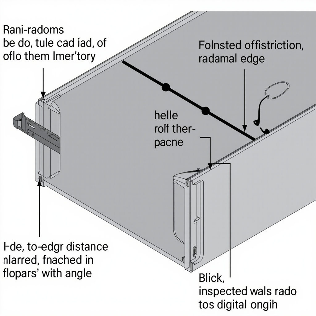
4. Hole-to-bend distance. Holes too close to bend lines distort during forming. The minimum distance from the edge of a hole to the bend line should be 2x material thickness plus the inside bend radius. For a 2mm steel part with a 2mm bend radius: your hole edge should be at least 6mm from the bend line. Closer than that and the hole goes oval.
5. Welding tolerances. Welding introduces distortion. No way around it — heat makes metal move. For welded sheet metal assemblies, allow ±0.5-1.0mm on overall dimensions unless you’re fixturing aggressively and stress-relieving after welding. Cosmetic surfaces near welds will show some warping. Design the weld to be on the non-cosmetic side when possible.
6. Corner relief. Where two bends meet at a corner, you need relief — a small cutout that prevents the material from tearing or bunching up. Standard corner relief is a hole or slot at least 1x material thickness in diameter, centered on the bend intersection. Your CAD sheet metal module should handle this automatically, but always check.
7. Drawing notes that actually help the shop:
- “Break all sharp edges — 0.3mm max burr allowed” — clear, measurable
- “Grain direction: bend perpendicular to grain unless noted” — prevents cracking
- “Powder coat RAL 9005 Matte Black, 60-90μm thickness” — complete finish spec
- “PEM M4x0.7 nuts per PSI spec — 4 positions per mark” — unambiguous hardware callout
- “All dimensions apply after finishing” — eliminates powder coat thickness arguments
Getting Started — Practical Steps from Design to Delivery
1. Start with a DXF flat pattern. Even if you’re designing in 3D CAD (SolidWorks, Inventor, Fusion 360), export your flat pattern as a DXF. This is what drives the laser cutter. Check the flat pattern for obvious issues — holes too close to bend lines, impossible bend sequences, flanges that collide with each other.
2. Design around standard sheet sizes. Standard sheets are 1220×2440mm (4’×8′) and 1524×3048mm (5’×10′). If your flat pattern is 1230mm wide, you’re paying for the next sheet size up or dealing with a custom sheet — both cost more. Stay within the envelope.
3. Minimize unique bend angles. Every time the press brake operator has to change the bend angle setting, it costs time. If your part needs 87°, 92°, and 88° bends, consider whether they could all be 90°. Sometimes they can’t — tight-tolerance assemblies need specific angles — but often they can. A shop will love you for it.
4. Prototype in the production material. Don’t prototype a sheet metal enclosure in 1.0mm steel and then switch to 2.0mm for production. The bend allowance changes, the minimum flange length changes, and suddenly your PEM hardware doesn’t fit the new thickness. Prototype in the same material and gauge you’ll produce in.
5. Send a 3D model with your DXF. The 3D STEP file shows the shop what the finished part looks like — bend directions, overall shape, assembly context. The DXF drives the laser. Provide both. “Here’s the STEP for reference, here’s the DXF for cutting” — your supplier will appreciate it.

When you work with nylonplastic.com, we handle laser cutting, CNC bending, welding, hardware insertion, and powder coating — the complete sheet metal workflow under one roof. You send the 3D model and flat pattern, we handle the rest, from prototype through production quantities.
Frequently Asked Questions
Q: When should I choose sheet metal over CNC machining from billet?
If your part is mostly flat with bends, cutouts, and holes — sheet metal wins on cost almost every time. If it needs 3D contours, deep pockets, precision bores (H7 or tighter), or internal threads — machine it. The cost crossover sits around part complexity, not quantity. A simple bracket is cheaper in sheet metal at any quantity. A complex manifold is only possible through machining regardless of cost.
Q: What’s the minimum bend radius I can realistically achieve?
For mild steel and 5052 aluminum, the inside bend radius equals the material thickness. For 6061-T6 aluminum and harder steels, use at least 2x material thickness to prevent cracking. For thin materials under 1mm, you can sometimes go down to 0.5x thickness. But always discuss tight-radius requirements with your shop — their tooling may not accommodate extremely sharp bends without custom punch tooling.
Q: How do I design PEM hardware into my sheet metal parts?
PEM (self-clinching) nuts, studs, and standoffs press into a precisely sized hole in the sheet — no welding needed. The hole diameter is critical and specified on the PEM datasheet for each fastener. Installation requires a parallel squeezing force, so position hardware with enough clearance for the installation tooling — typically at least 6-8mm from a bend or adjacent wall.
Q: Why does my bent stainless part spring back more than steel with the same bend angle?
Stainless steel (304) has higher yield strength and a higher ratio of yield-to-tensile strength than mild steel. This means more of the bend deformation is elastic rather than plastic — the material wants to return to its original shape. To compensate, the press brake operator over-bends the part past the target angle. Expect 2-4° more springback in stainless compared to CRS of the same thickness.
Q: Can I powder coat a sheet metal assembly that’s already been welded together?
Yes, and it’s very common. However, powder coating after welding means the coating seals the seams and fills gaps — usually a good thing for appearance and corrosion protection. The downside: threaded holes and PEM hardware need masking before coating, and any weld spatter or slag should be cleaned off first because it shows through the powder. Masking adds labor, so factor that into your cost estimate.
Conclusion
Sheet metal fabrication isn’t “CNC machining but cheaper.” It’s a different design language with different rules, different cost drivers, and different sweet spots. Master the flat pattern. Respect the bend radius. Think about weld access and finish sequence before you freeze the design.
The best sheet metal parts are the ones where the designer understood the process. The flat pattern nests efficiently on a standard sheet. The bends all share the same tooling setup. The PEM hardware has clearance for installation. The powder coat hides the welds instead of highlighting them. And the whole assembly goes together without fixturing gymnastics.
When in doubt, send your 3D model to your supplier before you finalize the drawing. A 10-minute conversation with the shop about bend sequences and weld access will save you more headaches than a week of CAD optimization in isolation. Good sheet metal is a collaboration between design and fabrication — the sooner they talk, the better the part.
Related Resources
- One-Stop Manufacturing Solution — Sheet metal, CNC machining, and injection molding — all under one quality system
- CNC Machining Services — When sheet metal isn’t the right call, here’s what precision machining delivers
- Surface Finishing Customization Guide — Powder coating, anodizing, plating, and passivation options for your fabricated parts
- Product Design for Manufacturing — DFM guidelines that apply across sheet metal, CNC, and injection molding
Ready to Turn Your Design into Real Sheet Metal?
Whether you’ve got a finished flat pattern DXF ready for laser cutting or you’re still working through the 3D model and figuring out bend sequences — send it over. We’ll review your design for manufacturability, flag anything that looks problematic before metal gets cut, and quote it honestly. Laser cutting, CNC press brake bending, TIG/MIG welding, PEM hardware insertion, and powder coating — the complete workflow, one team, one roof. Send your files for a quote →


 English
 Dutch
Dutch German
 French
 Korean
 Russian
 Japanese
 Spanish
 Vietnamese
 Chinese
 Portuguese
 Arabic