
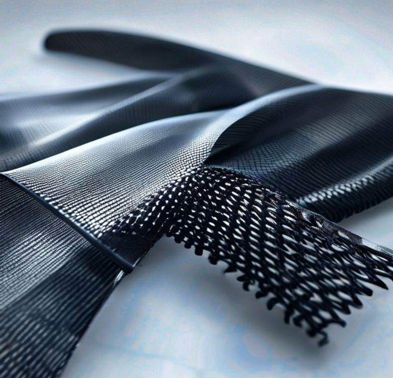
Technical comparison of glass fiber and carbon fiber reinforced nylon — strength, stiffness, thermal, cost, and application guidance.
Why Reinforce Nylon? The Performance Gap
Unfilled nylon is an excellent general-purpose engineering plastic, but its modulus (2.8-3.0 GPa) and thermal resistance (HDT 65°C at 1.82 MPa) fall short for structural and high-temperature applications. Reinforcement fillers — glass fiber and carbon fiber — close this gap dramatically.
The choice between glass fiber and carbon fiber reinforcement is one of the most consequential material decisions in precision engineering. It determines stiffness, strength, dimensional stability, weight, cost, and processing characteristics. This guide provides the complete comparison engineers need.
Material Composition and Cost Comparison
Typical Compositions:
| Material | Reinforcement | Tensile Strength | Tensile Modulus | Specific Strength |
|---|---|---|---|---|
| Unfilled PA66 | None | 82 MPa | 3.0 GPa | 28 |
| PA66-GF30 | 30% Glass Fiber | 185 MPa | 10.0 GPa | 76 |
| PA66-CF30 | 30% Carbon Fiber | 220 MPa | 17.0 GPa | 118 |
| PA6-GF30 | 30% Glass Fiber | 170 MPa | 9.0 GPa | 70 |
| PA6-CF30 | 30% Carbon Fiber | 200 MPa | 15.5 GPa | 108 |
*Specific Strength = Strength-to-weight ratio (MPa / g/cm³)
Cost Analysis (approximate, USD/kg):
| Material | Price Range | Notes |
|---|---|---|
| — | — | Unfilled PA66 |
| $3-5 | Baseline | PA6-GF30 |
| $4-7 | ~40% premium | PA66-GF30 |
| $4.5-8 | Most common reinforced nylon | PA6-CF30 |
| $18-30 | Carbon fiber premium | PA66-CF30 |
| $20-35 | Premium specialty | Aluminum 6061 |
| $5-8 | Metal comparison |
Key insight: Carbon fiber nylon costs 4-7× more than glass fiber nylon but provides only 20-30% higher strength and 50-70% higher stiffness. The premium is justified primarily when weight reduction, ESD properties, or reduced warpage are critical requirements.
Mechanical Properties: Strength, Stiffness, and Toughness
Strength and Stiffness: Carbon fiber reinforced nylon outperforms glass fiber in every mechanical property, but the margin varies:
- Tensile strength: CF30 is 20-30% stronger than GF30
- Tensile modulus (stiffness): CF30 is 55-70% stiffer than GF30
- Flexural strength: CF30 is 15-25% higher than GF30
- Flexural modulus: CF30 is 50-65% higher than GF30
The stiffness advantage is particularly significant — CF30 reaches 17 GPa, approaching aluminum (69 GPa), while GF30 maxes out at 10 GPa. For stiffness-critical applications requiring metal replacement, CF30 may be the only viable plastic option.
Impact and Toughness: Both reinforced materials have lower impact resistance than unfilled nylon (fiber reinforcement reduces ductility):
| Property | Unfilled PA66 | PA66-GF30 | PA66-CF30 |
|---|---|---|---|
| Notched Izod (J/m) | 45 | 105 | 70 |
| Unnotched Izod (J/m) | No break | 700 | 450 |
| Elongation at Break (%) | 60 | 3 | 2 |
GF30 maintains better impact resistance than CF30 because glass fiber absorbs more impact energy through debonding. CF30 is stiffer but more brittle.
Glass vs Carbon Fiber Nylon CNC Machining Nylon Tips Food Grade Plastics Guide PEEK Plastic Guide Engineering Plastics Buying Guide
Dimensional Stability and Warpage Control
This is where carbon fiber shows its most decisive advantage.
Thermal Expansion:
| Material | Thermal Expansion (×10⁻⁵/°C) | vs. Aluminum 6061 |
|---|---|---|
| Unfilled PA66 | 8–10 | 4–5× higher |
| PA66-GF30 | 2–3 | 1–1.5× |
| PA66-CF30 | 0.5–1.5 | 0.25–0.75× |
| Aluminum 6061 | 2.3 | Baseline |
CF30’s thermal expansion coefficient approaches that of aluminum and steel. This means parts made from CF30 change dimensions less with temperature variation — critical for precision components and assemblies with metal inserts.
Warpage and Shrinkage Anisotropy: Glass fiber causes differential shrinkage: parts shrink less in the flow direction (where fibers are oriented) than perpendicular to flow. This creates warpage, especially in flat parts with uneven cooling or asymmetrical gating.
Carbon fiber causes less anisotropy because carbon fibers are smaller and more uniformly dispersible. CF30 parts show 40-60% less warpage than equivalent GF30 parts.
For flat panels, large structural components, and precision-machined parts: CF30 is significantly easier to mold to tolerance without post-machining.
Electrical and Special Properties
Electrical Conductivity / ESD: This is the unique advantage of carbon fiber reinforcement:
| Property | Unfilled PA66 | PA66-GF30 | PA66-CF30 |
|---|---|---|---|
| Volume Resistivity | 10^15 Ω·cm | 10^14 Ω·cm | 10^2-10^4 Ω·cm |
| Surface Resistivity | 10^13 Ω | 10^12 Ω | 10^3-10^5 Ω |
| ESD Category | Insulator | Insulator | Static Dissipative |
Carbon fiber at 30% loading creates a conductive network within the nylon matrix. Parts become static-dissipative (SDS, 10^5-10^11 Ω), eliminating static electricity buildup that attracts dust, damages electronics, or causes sparks in flammable environments.
ESD Applications for CF Nylon: – Electronics component trays and carriers – Fuel system components (prevents static spark ignition) – Cleanroom equipment (prevents contamination from static attraction) – Conveyor guides and rollers in printing/packaging
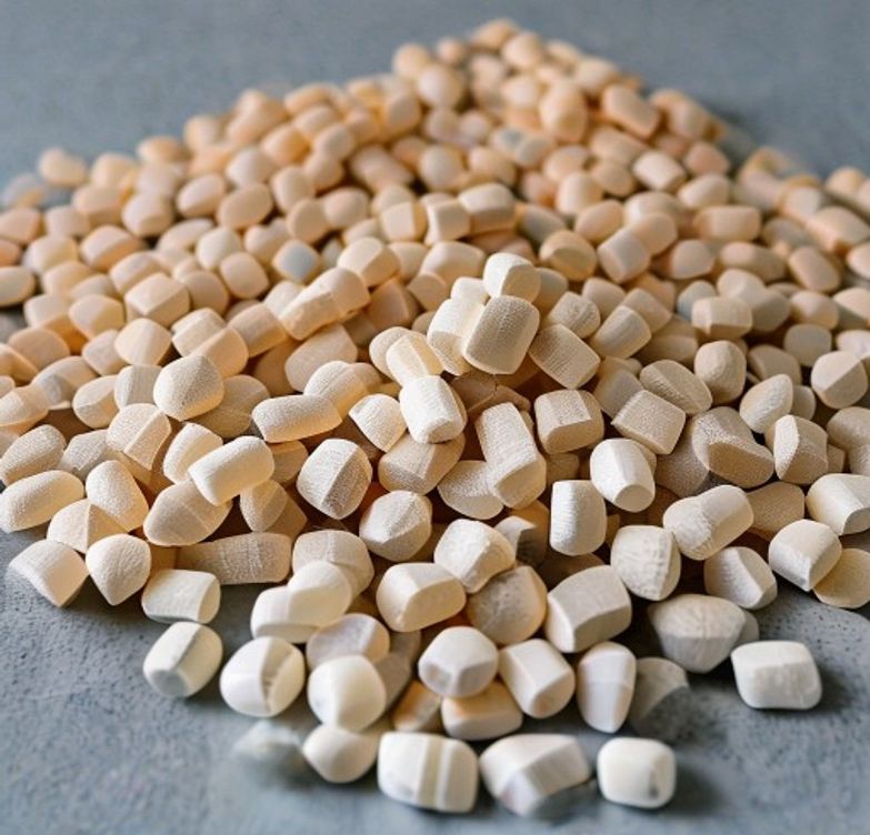
nylonplastic.com’s CF Nylon (PA6-CF and PA12-CF) is specifically formulated for ESD applications, with consistent resistivity across the part surface and after moisture conditioning.
Processing and Application Recommendations
Injection Molding Guidelines:
| Parameter | PA66-GF30 | PA66-CF30 |
|---|---|---|
| Melt Temperature (°C) | 275–295 | 270–290 |
| Mold Temperature (°C) | 80–100 | 80–100 |
| Injection Pressure | High | High |
| Back Pressure | Moderate | Moderate |
| Screw Compression Ratio | 2.0–2.5 | 1.8–2.2 |
| Nozzle Requirement | Standard | Hardened (CF abrasive) |
| Gate Size | Larger than unfilled | Larger than GF |
Machining: CF30 is significantly harder to machine than GF30 — carbide or diamond tooling required. Glass fiber is abrasive but manageable with solid carbide. Carbon fiber tends to delaminate and fray at machined edges.
Design Recommendations by Application:
Choose GF30 when: – Budget is constrained – Standard structural stiffness is sufficient (10 GPa) – Impact resistance is important – Large-part injection molding with complex geometry
Choose CF30 when: – Metal-replacement stiffness is required (17 GPa approaches aluminum) – Dimensional stability across temperature is critical – ESD/conductivity is required – Weight reduction is a priority (CF is 30% lighter than glass fiber at equal stiffness) – Low warpage in large flat parts
Engineering-grade nylon raw materials for injection molding
ESD properties + 5x stiffness — specialty line
Frequently Asked Questions
When should I choose carbon fiber reinforcement over glass fiber?
Choose carbon fiber when: maximum stiffness-to-weight critical, weight reduction target 20-30%, thermal conductivity needed (heat dissipation), electrical conductivity acceptable. Choose glass fiber when: maximum impact resistance needed, cost is primary driver, electrical insulation required, or processing ease is priority.
How do processing requirements differ between glass and carbon fiber nylon?
Both require hardened nozzles (ruby or diamond). Carbon fiber: higher abrasive wear than glass fiber. Drying: PA6-CF critical (80°C, 4-6h). Processing: PA6-CF lower melt temperature (260°C) than PA6-GF30 (275°C) to minimize thermal degradation of carbon fibers. PA6-GF30 tolerates higher processing temperatures.
Are there electrical conductivity benefits with carbon fiber reinforcement?
Yes. PA6-CF surface resistivity: 10²-10⁴ Ω·cm (semiconductive). PA6-GF: >10¹⁴ Ω·cm (electrical insulator). Carbon fiber reinforcement enables EMI shielding (attenuation 40-60 dB at 1 GHz) without added conductive fillers. Use for EMI-shielded enclosures.
What are the cost implications of carbon fiber vs glass fiber nylon?
PA6-CF: $40-80/kg vs PA6-GF30: $5-15/kg. Carbon fiber premium: 4-5x glass fiber on per-kg basis. However, thinner-walled PA6-CF designs can use 30-40% less material, partially offsetting premium. Total part cost analysis required.
How do I account for anisotropic shrinkage in fiber reinforced nylon?
Mold shrinkage is anisotropic: in flow direction: 0.2-0.4% (CF), 0.3-0.5% (GF). Transverse: 0.5-0.8% (CF), 0.8-1.2% (GF). Design for transverse shrinkage in both dimensions. Balance flow with fan-gate placement. Critical dimensions: post-machine after first shot.


 English
 Dutch
Dutch German
 French
 Korean
 Russian
 Japanese
 Spanish
 Vietnamese
 Chinese
 Portuguese
 Arabic