
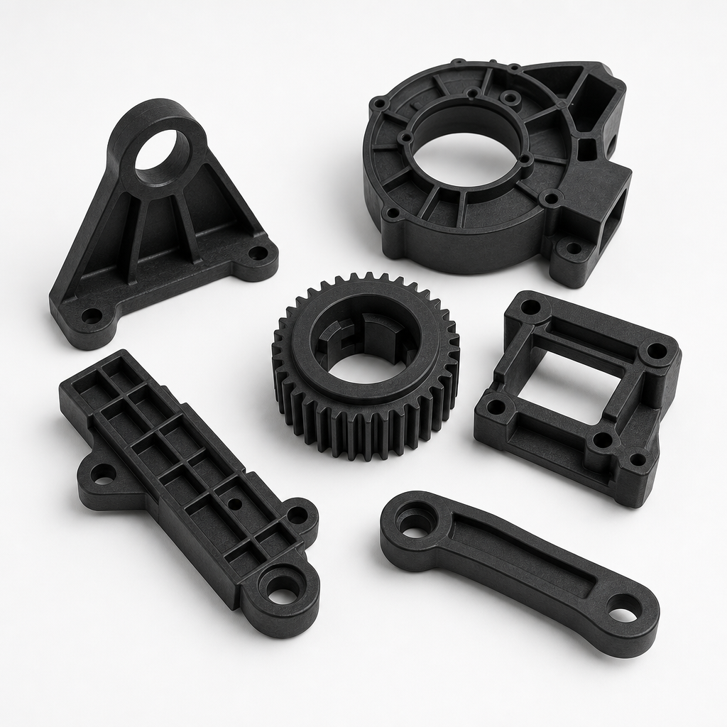
Adding glass fiber to nylon transforms a tough, wear-resistant engineering plastic into a structural material that competes with die-cast metals. At 30% glass loading, PA66-GF30 doubles tensile strength (80 to 165-185 MPa), triples flexural modulus (2.8 to 8-9 GPa), and pushes the heat deflection temperature from 75 degree C to over 240 degree C. These numbers explain why glass-filled nylon has replaced aluminum in automotive intake manifolds, power tool housings, and structural brackets across every industry where weight reduction meets structural demand.
For grade selection and production planning
Compare Glass-Filled Nylon Grades Before You Specify a Material
Tell us whether you are comparing PA6 or PA66 and GF20, GF30 or GF50. Share the application, operating temperature, load, moisture or chemical exposure, color, and required documents. We can identify the exact grade and technical data sheet that should be reviewed before purchase or part approval.
But glass fibers are a double-edged sword: they make nylon anisotropic (strength varies with flow direction), abrasive to molds and tooling, and more brittle at low temperatures. This guide covers the grades, design rules, and processing considerations that separate a reliable GF nylon part from one that fails at the knit line.
If the first decision is whether to reinforce the part at all, start with our glass-filled vs unfilled nylon comparison before selecting a fiber loading.
Data-sheet note: the values below are typical ranges, not a substitute for the technical data sheet of the final grade. Matrix resin, fiber sizing, test direction, moisture state, heat stabilization, impact modification, and color can change the result.
GF20 vs GF30 vs Higher Glass Loadings
| Loading | Typical Selection Reason | Main Tradeoff |
|---|---|---|
| GF15-GF20 | Moderate stiffness increase while retaining more toughness and flow | Lower structural margin than GF30 |
| GF30 | Common balance for structural molded parts | More anisotropy, abrasion, and visible fiber texture |
| GF40-GF50 | Maximum stiffness or lower shrinkage in a qualified geometry | Harder processing, lower impact tolerance, and higher tool wear |

Glass Fiber Loading: What Each Percentage Delivers
PA66-GF15: Often selected when moderate reinforcement and retained toughness matter. PA66-GF30: A common structural loading when stiffness, molding behavior and availability must be balanced. PA66-GF50: Considered when a qualified part still needs more stiffness. Higher glass loading can reduce flow, increase anisotropy and tooling wear, and change impact behavior. Compare exact-grade datasheets tested by the same impact method and conditioning state; the table below is a screening reference, not proof that GF50 has a fixed impact penalty versus GF30.
Property Comparison by Glass Loading
| Property | PA66 Unfilled | PA66-GF15 | PA66-GF30 | PA66-GF50 | Aluminum (ref) |
|---|---|---|---|---|---|
| Tensile Strength (MPa) | 80-85 | 120-130 | 165-185 | 210-230 | 240-320 |
| Flexural Modulus (GPa) | 2.8-3.0 | 5.0-6.0 | 8.0-9.0 | 14.0-16.0 | 70 |
| HDT @ 1.82 MPa (deg C) | 70-80 | 230-240 | 240-250 | 250-255 | N/A |
| Notched Izod (kJ/m2) | 4-6 | 5-7 | 8-12 | 10-14 | N/A |
| Density (g/cm3) | 1.14 | 1.23 | 1.37-1.38 | 1.55-1.57 | 2.70 |
| Mold Shrinkage (%) | 1.5-2.0 | 0.4-0.8 | 0.2-0.6 | 0.1-0.3 | N/A |
| CTE (10^-6/deg C) | 70-90 | 30-40 | 20-30 | 15-20 | 21-24 |
Fiber Orientation: The Hidden Design Variable
Glass fibers align with the melt flow direction during injection, creating anisotropic mechanical properties. A PA66-GF30 tensile bar tested parallel to flow direction shows 180 MPa; the same material tested perpendicular to flow shows 80-100 MPa – a 45-55% reduction. This anisotropy must be accounted for in part design and FEA analysis. Design implication: orient the part in the mold so that the primary load path aligns with the flow direction. Use multiple gates to control fiber orientation when loads are multi-axial, but be aware that knit lines (where flow fronts meet) contain no fiber bridging and have only 50-60% of the base strength.
Design Rules for Glass-Filled Nylon
- Account for anisotropic shrinkage: GF nylon shrinks 2-4x more in the transverse direction than along flow. A 100 mm feature parallel to flow may shrink 0.3 mm; the same feature perpendicular may shrink 1.0 mm. Apply different shrinkage factors for flow and transverse directions in mold design, or use mold flow simulation to predict differential shrinkage.
- Avoid sharp corners at knit lines: Knit lines in GF nylon contain no fiber bridging – the two flow fronts meet with only matrix polymer at the interface. A radius of 0.5 mm minimum at knit line locations reduces stress concentration from Kt=3-4 down to Kt=1.5-2. Move knit lines away from high-stress areas by repositioning gates.
- Specify hardened mold steel: GF30 and above is abrasive. P20 steel (HRC 28-32) wears measurably after 50,000-100,000 shots. Use H13 (HRC 48-52) or D2 (HRC 58-62) for cavities expected to exceed 100,000 cycles. For GF50, even H13 shows wear at 50,000 cycles – consider stainless steel with nitriding or hard chrome plating on wear surfaces.
- Design for warpage control: The differential shrinkage between flow and transverse directions causes GF nylon parts to warp. Three countermeasures: (1) Uniform wall thickness (plus or minus 15% maximum variation). (2) Balanced filling with symmetric gate locations. (3) Cooling channels positioned for uniform temperature across the cavity. Mold flow simulation is strongly recommended for GF30+ parts with wall sections over 2 mm.
- Gate location determines part strength: Position gates to align fiber orientation with primary load paths. Edge gates produce unidirectional orientation parallel to flow; fan gates produce radial orientation – choose based on whether loads are uniaxial or multi-axial. A poorly placed gate that creates a knit line at a load-bearing boss can reduce local strength by 50% versus the datasheet value.
- Moisture conditioning still matters: GF nylon absorbs less moisture than unfilled (1.5-2.5% vs 2-8% at saturation) because glass fibers displace hygroscopic polymer. But the PA66 matrix still absorbs water and swells – dimensional change is roughly proportional to the nylon fraction by volume. A GF30 part (70% nylon by volume) experiences roughly 70% of the moisture expansion of an unfilled part. Condition GF nylon parts to equilibrium moisture before critical dimensional inspection.
Industry Application Matrix
| Industry | Typical Parts | Material/Grade | Key Requirement |
|---|---|---|---|
| Automotive | Intake manifolds, engine covers, radiator end tanks, mirror housings | PA66-GF30 | 250 deg C HDT, glycol resistance, weld-line strength |
| Power Tools | Housings, gear cases, handle frames | PA6-GF30 | Impact at -20 deg C, vibration damping, UL 94 HB |
| Industrial Equipment | Pump housings, structural brackets, conveyor components | PA66-GF50 | Creep resistance under sustained load, chemical exposure |
| Consumer Goods | Appliance structural frames, furniture mechanisms | PA6-GF15 or GF30 | Cost-to-strength ratio, colorability, tactile feel |
The cheapest resin grade is not always the lowest-cost molded part.
Send the drawing, load direction, cosmetic requirement and annual volume. We can review glass loading, gate strategy, warpage risk and mold steel before tooling is released.
Cost Decision Framework
Material cost: PA66-GF30: $4.50-7.00/kg (vs $3.00-4.50 for unfilled PA66). PA66-GF50: $6.00-9.00/kg. The glass fiber premium is 50-100% over unfilled, but the strength improvement is 100-150% – the strength-per-dollar ratio actually improves with GF content for load-bearing parts.
Processing cost: GF grades require 10-20 deg C higher melt temperatures, slightly longer cycle times, and more frequent screw/barrel replacement (every 500-1,000 tons of material vs 2,000-3,000 for unfilled). The mold steel upgrade (P20 to H13) adds $2,000-8,000 to mold cost but is essential for volumes above 100,000.
Selection approach: Evaluate GF15 when moderate stiffness and retained ductility matter. Evaluate GF30 when the part needs a common structural balance. Evaluate GF50 only when the higher stiffness is useful in the actual geometry and the project can accept its flow, anisotropy, surface and tooling trade-offs. Compare impact data only when the grade, method, notch, specimen direction and conditioning are aligned.
Common Defects and Solutions
| Defect | Appearance | Root Cause | Solution |
|---|---|---|---|
| Warpage / bowing | Part curves or twists | Anisotropic shrinkage: flow vs transverse | Gate centrally for symmetrical fill; use mold flow analysis; uniform cooling |
| Knit line weakness | Part cracks at flow-front meeting line | No fiber bridging; stress concentration | Move gate to relocate knit line; add radius over 0.5mm; increase melt temp 10-15 deg C |
| Surface glass fiber appearance | Visible fibers on part surface; roughness | Low mold temperature; high fiber content at surface | Increase mold temp to 120-140 deg C; use fast fill speed; GF15 max for cosmetic surfaces |
| Mold wear / erosion | Cavity dimensions growing; flashing increasing | Glass fiber abrasion on P20 steel | Upgrade to H13 or D2 steel; hard chrome plate gate area; inspect after 50K shots |
Specification Gaps That Cause Glass-Filled Nylon Projects to Fail
| Specification Gap | Project Risk | How Nylon Plastic Supports the Review |
|---|---|---|
| The RFQ says only “PA66-GF30” | Heat stabilization, impact, color, approvals, and conditioning remain undefined | Review the complete grade and documentation requirement before quotation |
| A higher GF percentage is chosen from tensile strength alone | Unexpected brittleness, weld-line weakness, or poor surface finish | Compare unfilled PA, GF20, GF30, and higher loadings against the real failure mode |
| Flow direction is ignored | Warpage and mechanical performance differ across the part | Connect material selection with gate, flow, wall, and load-direction review |
| Moisture and lot controls are missing | Splay, degradation, dimensional variation, and inconsistent approval results | Define drying, COA, incoming inspection, and lot-approval expectations in the RFQ |
Nylon Plastic has supported material modification and finished-part manufacturing since 2005. Custom compounding and in-house process knowledge help connect the resin decision with molding, CNC machining, or 3D-printing validation when a standard grade is not enough.
Why Choose Nylon Plastic for Your Project
Precision Manufacturing
30+ CNC & injection molding cells under one roof
ISO 9001:2015 Certified
Certified quality system, full inspection reports
15-25 Day Lead Time
Fast turnaround with expedited options available
Global Shipping
Air & sea freight to North America, Europe, Asia
Download Our Glass-Filled Nylon Guide
Free PDF reference guide with technical data, design rules, and supplier checklists.
Frequently Asked Questions
What is glass-filled nylon and why use it?
Glass-filled nylon is nylon (PA66 or PA6) compounded with short glass fibers – typically 15%, 30%, or 50% by weight. The fibers increase tensile strength 50-150%, triple stiffness, and raise the heat deflection temperature from roughly 75 deg C to over 240 deg C. This transforms nylon from a tough, general-purpose engineering plastic into a structural material that replaces die-cast metals and thermoset composites in load-bearing applications. The cost premium (50-100% over unfilled nylon) is lower than the performance gain, making GF nylon the most cost-effective structural thermoplastic by strength-per-dollar.
Which glass fiber percentage should I choose?
GF15 is a useful comparison when the part needs more stiffness but still relies on ductility, flow or surface quality. GF30 is a common structural starting point. GF50 may be appropriate when higher stiffness is required and the part, gate and tooling can accommodate the processing trade-offs. Do not choose from glass percentage alone: compare exact-grade tensile, impact, moisture and thermal data under matched test conditions, then validate molded samples.
Does glass-filled nylon still absorb water?
Yes, but proportionally less than unfilled nylon. At saturation, PA66-GF30 absorbs 1.5-2.5% moisture versus 2-8% for unfilled PA66. The glass fibers do not absorb water, so the moisture uptake is proportional to the nylon fraction by volume (roughly 70% for GF30). The absorbed moisture still causes dimensional swelling (roughly 70% of unfilled rates) and reduces strength (conditioned PA66-GF30 tensile drops from roughly 180 MPa dry to roughly 120-140 MPa at 50% RH). Glass-filled nylon does not eliminate moisture sensitivity – it reduces it in proportion to the glass content.
How do you prevent mold wear from glass-filled nylon?
Glass fibers (Mohs hardness 6.5) act as a mild abrasive with every shot. Countermeasures by volume: Under 50,000 shots – P20 steel (HRC 28-32) is adequate but will show measurable wear. 50,000-200,000 shots – Use H13 steel (HRC 48-52) for cavities and cores. Over 200,000 shots – H13 with nitriding or hard chrome plating on wear surfaces (gate, runners, high-velocity areas). For GF50 at any volume, H13 is the minimum. Regular inspection intervals: measure critical cavity dimensions every 25,000 shots and resurface or replace at 0.05 mm wear.
Related Reading
Glass-Filled Nylon Products and Material Support
- PA6 GF20 product page
- PA66 GF20 product page
- PA6 GF30 product page
- PA66 GF30 product page
- Modified nylon granules and PA compounds

Prepare a production review
Request a Glass-Filled Nylon Review
Send the details below so fiber loading, flow direction, weld lines, warpage and tool wear can be reviewed before tooling release.
We can compare unfilled PA, GF20, GF30 and higher loadings without assuming that more glass fiber is always better.

